Dust separator in vacuum cleaner

A vacuum cleaner and separation device technology, applied in the direction of vacuum cleaners, suction filters, cleaning equipment, etc., can solve the problems that large particles are easily entrained by the air flow, carried away, and affect the separation effect, so as to achieve improved separation effect, reasonable structure, and improved The effect of the separation effect

Inactive Publication Date: 2010-06-09
沈建明
View PDF2 Cites 21 Cited by
  • Summary
  • Abstract
  • Description
  • Claims
  • Application Information

AI Technical Summary

Problems solved by technology

After being sucked into the inner cavity of the front-stage cyclone bucket, the heavier and large-particle dust will spiral downward, and the heavier particle dust will stay at the bottom of the back-stage cyclone bucket, so the front-stage cyclone separation part can play a role There is a further improvement on the separation of large and heavy particles of dust. However, since large particles of dust are directly deposited in the front-stage cyclone barrel without guides, large particles are easily entrained by the airflow, and the rear-stage cyclone separator The dust outlet is directly facing the dust chamber, and it is easy to entrain the separated small particles of dust again, thus affecting the separation effect. Therefore, further improvement of the design is required.

Method used


Image

  • Dust separator in vacuum cleaner
  • Dust separator in vacuum cleaner
  • Dust separator in vacuum cleaner

Examples


Embodiment Construction

[0019] The present invention will be further described in detail below in conjunction with the accompanying drawings and embodiments.

[0020] Such as Figure 1~3 A preferred embodiment of the invention is shown.

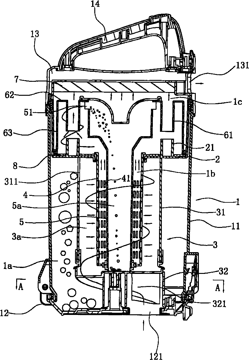
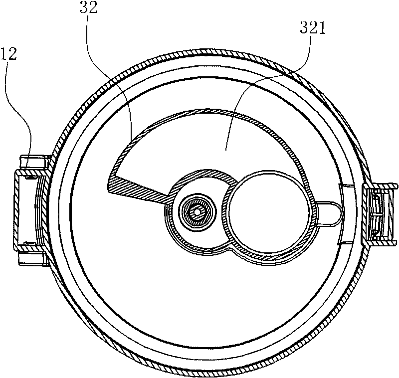
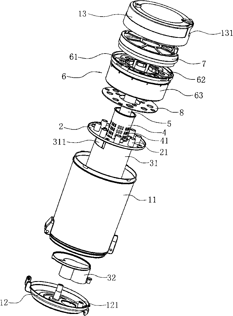
[0021] A dust removal and separation device in a vacuum cleaner, comprising a barrel body 1 provided with a total air inlet 121 and a total air outlet 131, a single cyclone separation structure arranged on the lower layer of the barrel body 1 and a parallel cyclone separation structure arranged on the upper layer of the barrel body 1 Structure, these are similar to traditional dust removal and separation devices;

[0022] The key point of the present invention is that the upper layer and the lower layer of the bucket body 1 are separated by a partition 2 .

[0023] The single cyclone separation structure is a dust cup 3 with a total air inlet channel 321 arranged on the lower layer of the barrel body 1. The best design is that the dust cup 3 is composed of a cup b...


PUM


Abstract

The invention relates to a dust separator in a vacuum cleaner, which comprises a bucket body, a single cyclone separation structure and a parallel cyclone separation structure, and is characterized in that an upper layer and a lower layer of the bucket body are separated by a clapboard; the lower layer of the bucket body is provided with a dust cup of which the upper part is provided with a discharge opening, and a cylindrical filter screen cover component is arranged in the dust cup; a primary cyclone channel is formed between the dust cup and the filter screen cover component, and a big dust collecting cavity is formed between the dust cup and the bucket body; an inner dust bucket of which the upper part is provided with an opening is arranged in the cylindrical filter screen cover component, a small dust collecting cavity is formed inside the inner dust bucket, and a secondary air guide channel is formed between the inner dust bucket and the filter screen cover component; and each air guide pipe of the parallel cyclone separation structure is communicated with the upper layer space of the bucket body and a main air outlet of the bucket body through a mixed gas chamber. In the separator of the invention, the small dust collecting cavity is arranged in the inner dust bucket positioned in the cylindrical filter screen cover component to fully utilize the space of the bucket body, thus the structure of the separator is more reasonable.

Description

technical field [0001] The invention relates to a dust removal and separation device in a vacuum cleaner. Background technique [0002] Due to the continuous improvement of people's living standards and the progress of science and technology, vacuum cleaners are gradually entering people's lives, families and workplaces. For this reason, scientific and technical personnel are constantly developing dust collection devices with new vacuum cleaners. [0003] For example, the Chinese invention patent "Equipment for Separating Particles from a Fluid Flow" with the application number CN01807570.3 (publication number CN1422187A) discloses such a device, which includes an upstream cyclone separator and a plurality of downstream cyclone separators arranged in parallel to each other. Cyclones, each downstream cyclone protruding at least partly into the interior of the upstream cyclone, this arrangement provides a compact and economical device, which is particularly suitable for applic...

Claims


Application Information

Patent Timeline
Patent Type & Authority Applications(China)
IPC IPC(8): A47L9/10A47L9/16
CPCA47L9/1608A47L9/165A47L9/1683
Inventor 沈建明
Owner 沈建明
Why Eureka
Try Eureka