
Material discharging device with air distribution function

A technology of unloading device and gas function, applied to the unloading device on the moving bed reactor, in the field of unloading device, it can solve the problems of no gas distribution function, blockage of the moving bed reactor, etc., to ensure fluency and avoid dead ends area, the effect of prolonging the gas-solid contact time

Inactive Publication Date: 2013-01-30
HARBIN INST OF TECH
View PDF0 Cites 0 Cited by
  • Summary
  • Abstract
  • Description
  • Claims
  • Application Information

AI Technical Summary

Problems solved by technology

[0003] The purpose of the present invention is to solve the problem that the existing unloading device has no gas distribution function. After installing an axial gas distribution device in the moving bed reactor, the smoothness of the movement of the solid-phase reactant will be caused. In severe cases, the solid-phase reactant will be blocked. Problems with moving bed reactors, and then provide a discharge device with gas distribution function

Method used


Image

  • Material discharging device with air distribution function
  • Material discharging device with air distribution function
  • Material discharging device with air distribution function

Examples


specific Embodiment approach 1

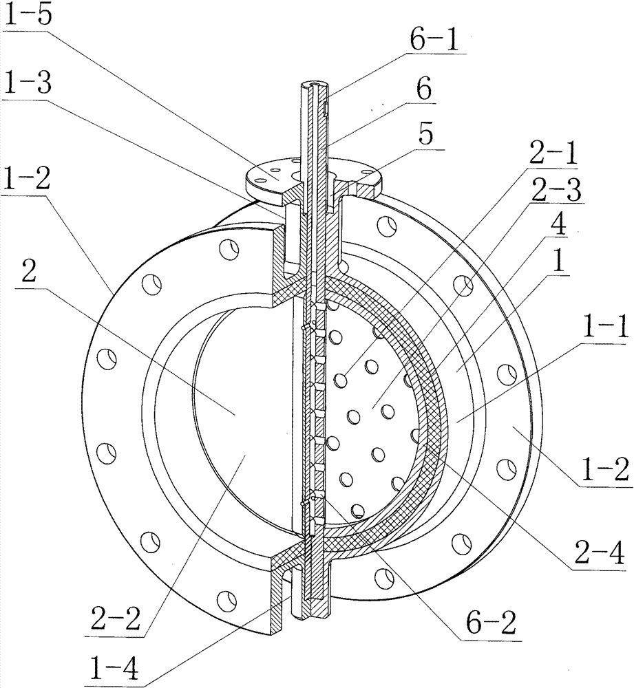
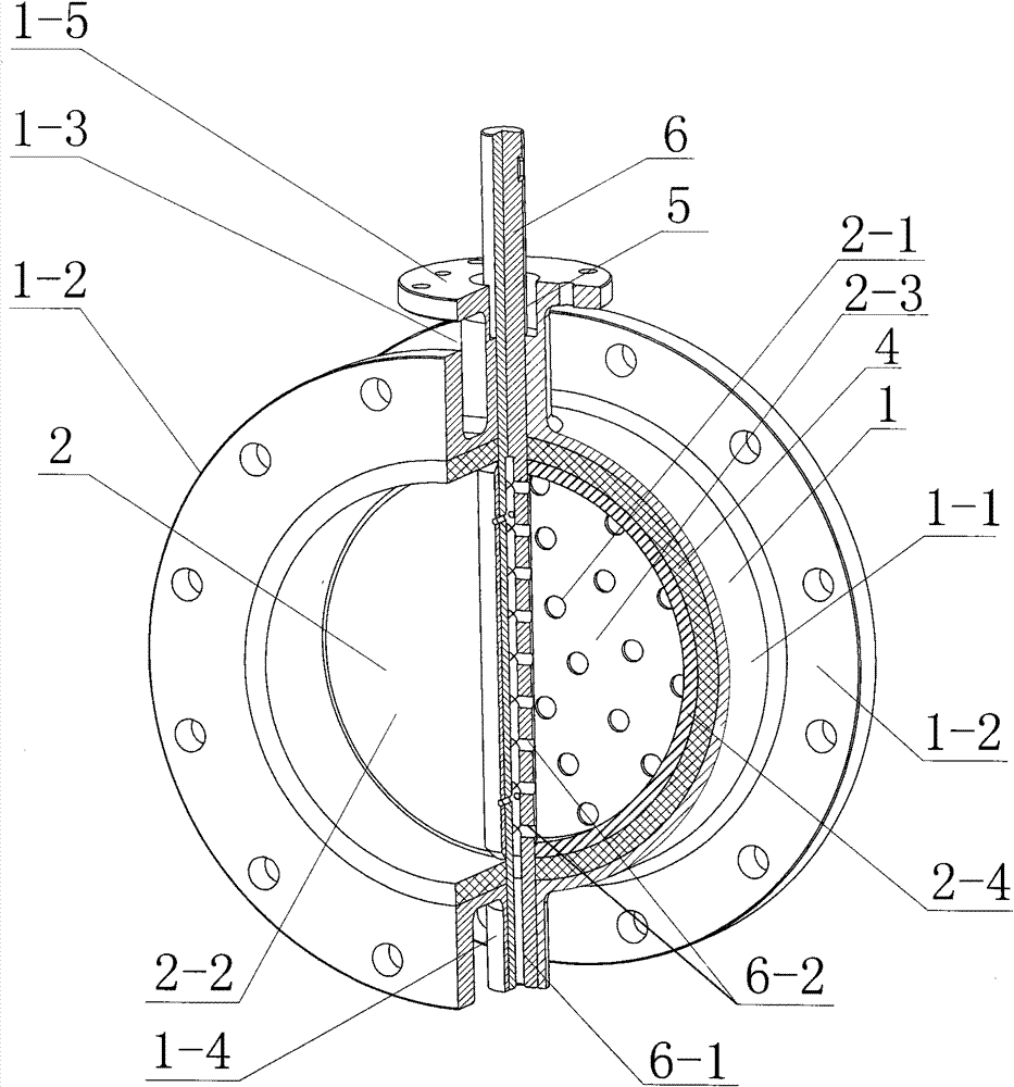
[0007] Specific implementation mode one: as Figure 1~6 As shown, the unloading device with air distribution function in this embodiment includes a device housing 1, a rotating shaft 6 and a plurality of hoods 14, and the device housing 1 consists of a cylinder 1-1, two large flanges 1-2, The first shaft sleeve 1-3, the second shaft sleeve 1-4 and the small flange 1-5 are composed, the cross section of the cylinder 1-1 is a ring, and the two large flanges 1-2 are parallel Fixed on both ends of the cylinder 1-1, the first sleeve 1-3 and the second sleeve 1-4 are arranged on the opposite side wall of the cylinder 1-1 in the radial direction, and the first sleeve 1 -3 and the second shaft sleeve 1-4 communicate with the inner cavity of the cylinder 1-1, the small flange 1-5 is fixed on the first shaft sleeve 1-3, and the discharge device also includes The air distribution cavity 2, the shape of the air distribution cavity 2 is in the shape of a round cake, and a plurality of fir...

specific Embodiment approach 2

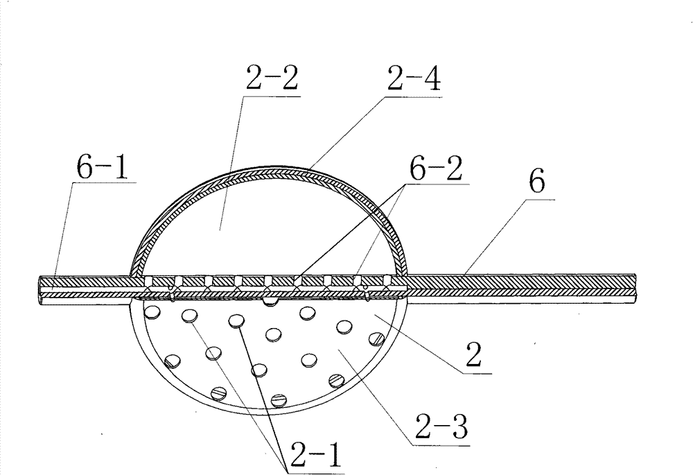
[0008] Specific implementation mode two: as Figure 1~3 As shown, the air distribution cavity 2 in this embodiment is composed of a valve plate 2-2, an air distribution plate 2-3 and a ring body 2-4, and the valve plate 2-2 is parallel to the air distribution plate 2-3 Setting, the valve plate 2-2 and the air distribution plate 2-3 are fixed together through the ring body 2-4 to form the air distribution cavity 2, and the air distribution plate 2-2 is provided with several evenly distributed The first through hole 2-1. With such a design, the valve plate 2-2 and the air distribution plate 2-3 are combined into one body, which has the function of unloading and air distribution. Other components and connections are the same as those in the first embodiment.

specific Embodiment approach 3

[0009] Specific implementation mode three: as Figure 4 As shown, the hood 14 in this embodiment is composed of a hood head 14-1 and a connecting end 14-2, the cross sections of the hood head 14-1 and the connecting end 14-2 are circular, and the hood head 14-1 communicates with the connection end 14-2, and a plurality of third through holes 14-3 are opened on the side wall of the hood head 14-1 along the circumferential direction. Such a design can change the direction of air outlet from the plurality of first through holes 2 - 1 on the air distribution cavity 2 , and can prevent solid-phase reactants from entering the air distribution cavity 2 . Other compositions and connections are the same as those in Embodiment 1 or 2.


PUM


Abstract

The invention belongs to a material discharging device with air distribution function, and relates to a material discharging device. The invention solves the problem that the prior material discharging device has no air distribution function; after an axial air distribution device is additionally arranged in a reactor of a moving bed, the moving smoothness of the solid reactants is influenced, and the reactor of the moving bed is blocked. One circular surface of a wind distribution cavity is provided with a plurality of first through holes in uniform distribution. The wind distribution cavity is arranged in an inner cavity of a barrel body in the radial direction, and the outer diameter thereof is equivalent to the inner diameter of the barrel body. A rotary shaft orderly penetrates through a first shaft sleeve, the wind distribution cavity and a second shaft sleeve, and is separately rotatably connected with the first shaft sleeve and the second shaft sleeve. The wind distribution cavity is fixedly connected with the rotary shaft. One end of the rotary shaft is provided with a long blind hole in the axial direction. Both side walls of the rotary shaft in the wind distribution cavity are provided with a plurality of second through holes in uniform distribution. The long blind hole is communicated with the wind distribution cavity through the second through holes. The invention realizes material discharging without obstacle and uniform wind distribution in the reactor of the moving bed, and the material after reaction can be discharged out of the reactor smoothly.

Description

technical field [0001] The invention relates to a discharge device, in particular to a discharge device for a moving bed reactor, belonging to the field of chemical environmental protection. Background technique [0002] In the field of chemical and environmental protection, the moving bed reactor is a common gas-solid reaction device. During the reaction process, the solid-phase reactant is continuously sent into the moving bed reactor through the feeding device, and the solid-phase reactant reacts with the gas entering the reactor from the bottom or upper part of the reactor. The reacted solid phase material is sent to the next process through the discharge valve. In this process, on the one hand, it is necessary to ensure that the reacted material can be smoothly discharged from the bed into the next process, and on the other hand, it is also necessary to ensure that the gas entering the reactor can fully contact with the material to complete the reaction. At present, d...

Claims


Application Information

Patent Timeline
Patent Type & Authority Patents(China)
IPC IPC(8): B01J8/02
Inventor 高继慧陈国庆尹伊郡高建民杜谦吴少华秦裕琨
Owner HARBIN INST OF TECH
Learn More