Flow passage of helical-tooth drip irrigation emitter

A technology of emitters and flow channels, which is applied in the field of helical drip irrigation emitter flow channels, can solve problems such as manufacturing complexity, and achieve the effects of improving hydraulic performance, reducing stagnant areas, and smooth flow

Active Publication Date: 2010-06-09
HOHAI UNIV
View PDF0 Cites 10 Cited by
  • Summary
  • Abstract
  • Description
  • Claims
  • Application Information

AI Technical Summary

Problems solved by technology

However, since the manufacture of this film-type drip irrigation belt product requires special production equipment, the manufacture is relatively complicated and difficult, so the flow channel structure of this p

Method used


Image

  • Flow passage of helical-tooth drip irrigation emitter
  • Flow passage of helical-tooth drip irrigation emitter
  • Flow passage of helical-tooth drip irrigation emitter

Examples


Embodiment 1

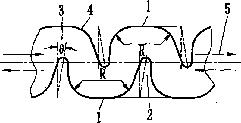
[0031] Such as figure 1 , figure 2 As shown, the trough-shaped flow channel formed by the boundary 1 and the flow channel depth 6 has protruding flow channel teeth 2 in the trough-shaped flow channel, and the dedendum of the flow channel teeth 2 forms an arc with the upper or lower boundary 1 Chamfer 4, a flow channel unit is composed of boundary 1, arc chamfer 4, runner teeth 2 and arc chamfer 4, the runner teeth 2 in the upper and lower runner units are arranged in a staggered manner, and several identical runner units are sequentially connected end to end to form an integral flow channel; the tooth tops of the flow channel teeth 2 are arc-shaped, and the tooth top arcs of the upper and lower flow channel teeth 2 extend into the other side of the center line of the flow channel; the flow channel The centerline of the road tooth 2 is inclined 15° to the right in the direction perpendicular to the centerline of the runner (of course, 0-45° to the left or right is valid), for...

Embodiment 2

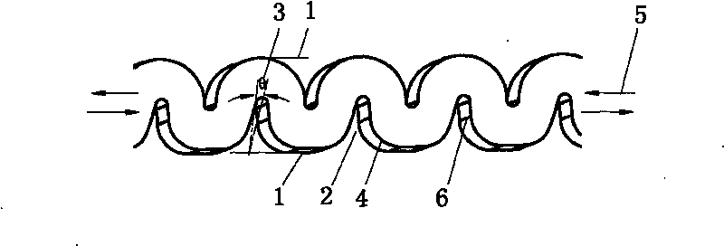
[0034] Such as image 3 , Figure 4 As shown, the basic structure is the same as that of Embodiment 1, and the difference from Embodiment 1 is that the upper boundary of the flow channel is in the shape of a semicircle. This change of the boundary can further improve the anti-clogging performance of the emitter. The x value of the channel structure of this embodiment is between 0.4792-0.4944.

Embodiment 3

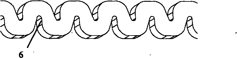
[0036] Such as Figure 5 , Figure 6 As shown, the basic structure is the same as that of Example 1, and the difference from Example 1 is that the upper and lower boundaries of the flow channel are both semi-circular arc-shaped. The change of this boundary can further improve the anti-clogging performance of the emitter, but the hydraulic performance will be affected, the x-values ​​drop somewhat, but not significantly. The x value of the channel structure of this embodiment is between 0.5129 and 0.5137.

[0037] In actual production, the above several embodiments can be selected and used according to local crop varieties and economic conditions.


PUM


Abstract

The invention relates to a flow passage of a helical-tooth drip irrigation emitter. An upper boundary, a lower boundary and a flow passage depth form a groove-shaped flow passage. The flow passage is characterized in that: raised flow passage teeth are arranged in the groove-shaped flow passage; dedendums of the flow passage teeth and the upper boundary or the lower boundary form circular arc chamfers, and flow passage units consist of the boundaries, the circular arc chamfers, the flow passage teeth and the circular arc chamfers; and the flow passage teeth in upper and lower flow passage units are arranged in a staggered mode, and a plurality of the same flow passage units are connected end to end sequentially to form an integral flow passage. A flow passage structure enables water flow in the flow passage to generate stronger turbulence effect under certain pressure, so that the hydraulic power performance of the emitter can be improved, and the blocking resistance of the emitter can be strengthened. The flow passage structure adopts a staggered helical-tooth shape, and angles of inclination of the flow passage teeth can be changed from 0 degree, and can incline towards two sides of a direction of a center line vertical to the flow passage to form different upstream faces and downstream faces of the flow passage, so that the hydraulic power performance of the emitter is changed and the blocking resistance of the emitter is improved.

Description

technical field [0001] The invention belongs to the technical field of agricultural machinery drip irrigation, and in particular relates to a flow path of a helical tooth drip irrigation dispenser. Background technique [0002] As we all know, drip irrigation is the most advanced high-standard irrigation technology in the world at present, and it is an effective way to develop cost-effective, high-yield, high-quality, and efficient agriculture. Countries all over the world are vigorously promoting this technology. In the drip irrigation system, the dripper is the tail equipment in the drip irrigation system and the key component of the drip irrigation system. Its performance directly affects the irrigation quality of the drip irrigation system. Dripper clogging has always been the main cause of equipment failure, and clogging is mainly caused by impurities in water, fertilizers, liquid medicines or chemical substances and microorganisms that block the narrow flow channels i...

Claims


Application Information

Patent Timeline
IPC IPC(8): B05B1/20B05B1/34
Inventor 方部玲金永奎孙艳玲齐松涛
Owner HOHAI UNIV
Why Eureka
Try Eureka