Electronic grade polysilicon reduction furnace base plate and reduction furnace

A polysilicon and reduction furnace technology, applied in the fields of silicon compounds, inorganic chemistry, chemical instruments and methods, etc., can solve the problems of low specific gravity of high-quality electronic-grade polysilicon, uneven temperature distribution on the surface of the silicon core, and high unit energy consumption of products. To achieve the effect of reducing unit energy consumption, reducing formation probability, location and quantity diversification

Pending Publication Date: 2019-01-04
QINGHAI HUANGHE HYDROPOWER DEV +2
View PDF7 Cites 0 Cited by
  • Summary
  • Abstract
  • Description
  • Claims
  • Application Information

AI Technical Summary

Problems solved by technology

However, there are defects in the design of these two chassis structures, which may easily cause poor gas flow in the furnace, weak gas flow circulation in the furnace, and more gas stagnation areas at the bottom and top of the reduction furnace, resulting in uneven temperature distribution on the surface of the silicon core and deposition The rate is low, which directly leads to the low proportion of high-quality electronic-grade polysilicon in each batch of polysilicon, and the unit energy consumption of the product is very high.

Method used


Image

  • Electronic grade polysilicon reduction furnace base plate and reduction furnace
  • Electronic grade polysilicon reduction furnace base plate and reduction furnace
  • Electronic grade polysilicon reduction furnace base plate and reduction furnace

Examples


Embodiment 1

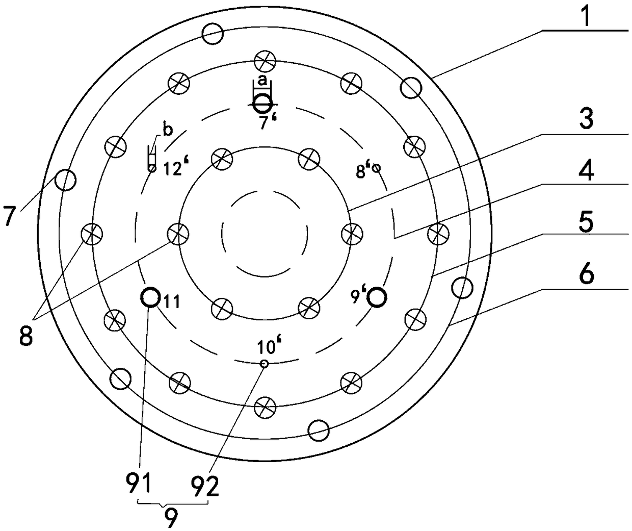
[0037] Such as figure 1 As shown, the polysilicon reduction furnace of this embodiment includes: a base plate 1 having a disc structure, and a first electrode ring 3, a first air inlet ring 4, a second electrode ring 5, and a first air outlet formed on the base plate 1. Ring 6; Among them, the first electrode ring 3, the first inlet ring 4, the second electrode ring 5 and the first outlet ring 6 are all concentric circles with the center of the chassis 1 as the center and set in sequence from the inside to the outside; Three pairs of electrodes 8 are uniformly arranged on one electrode ring 3, and six pairs of electrodes 8 are uniformly arranged on the second electrode ring 5; 6 mixed gas outlets 7 are uniformly arranged clockwise on the circumference of the first gas outlet ring 6.

[0038] On the circumference of the first air inlet ring 4, 6 mixed gas inlet nozzles are evenly arranged clockwise. The 6 mixed gas inlet nozzles are the first mixed gas inlet nozzle 7'and the second...

Embodiment 2

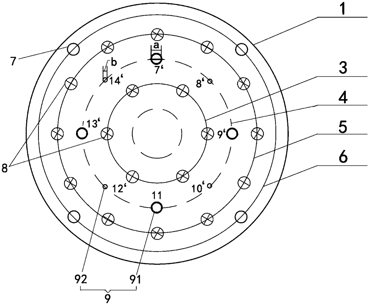
[0042] Such as figure 2 As shown, the polysilicon reduction furnace of this embodiment includes: a base plate 1 having a disc structure, and a first electrode ring 3, a first air inlet ring 4, a second electrode ring 5, and a first air outlet formed on the base plate 1. Ring 6; Among them, the first electrode ring 3, the first inlet ring 4, the second electrode ring 5 and the first outlet ring 6 are all concentric circles with the center of the chassis 1 as the center and set in order from the inside to the outside; Three pairs of electrodes 8 are uniformly arranged on one electrode ring 3, and six pairs of electrodes 8 are uniformly arranged on the second electrode ring 5; 4 mixed gas outlets 7 are uniformly arranged clockwise on the circumference of the first gas outlet ring 6.

[0043] On the circumference of the first inlet ring 4, there are 8 mixed gas inlet nozzles evenly arranged in a clockwise direction. The 8 mixed gas inlet nozzles are the No. 1 mixed gas inlet nozzle 7...

Embodiment 3

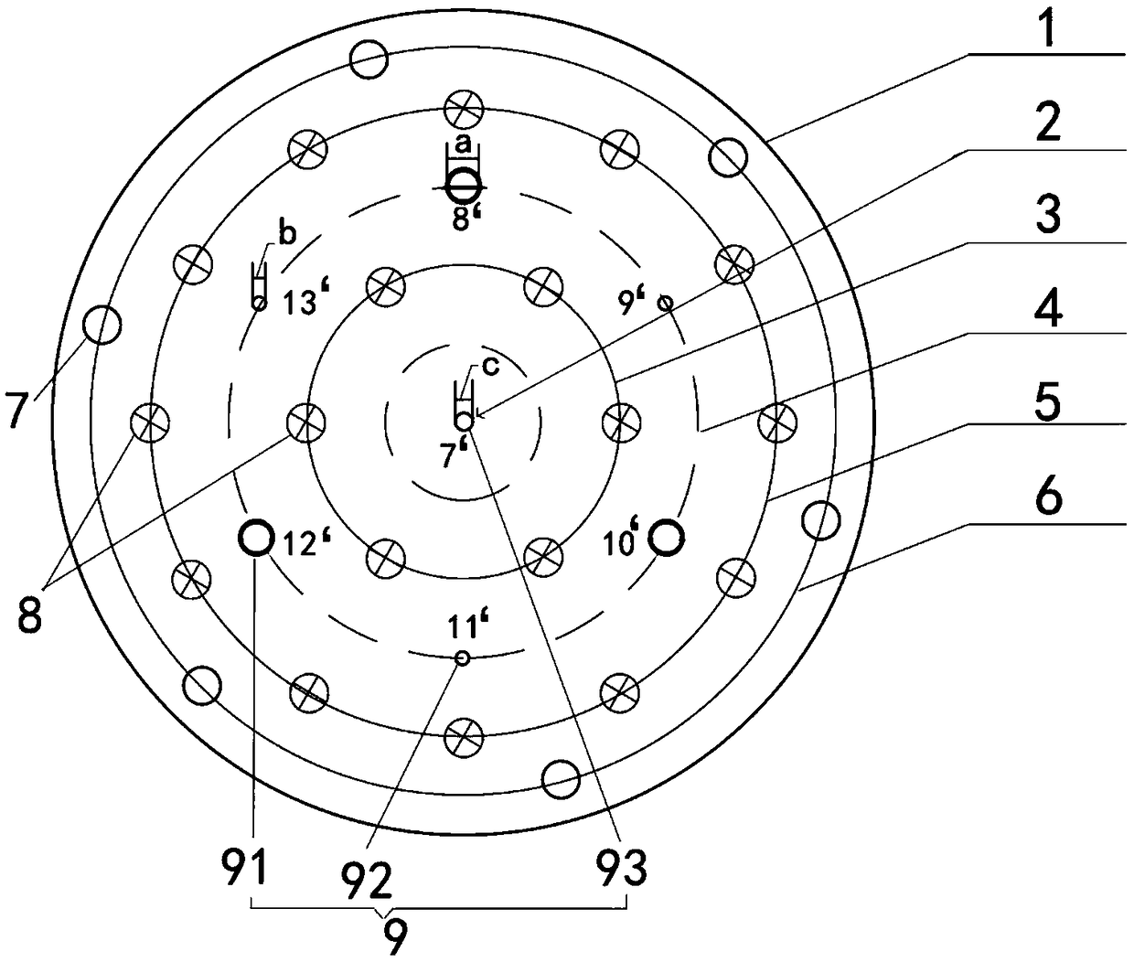
[0047] Such as image 3 As shown, the polysilicon reduction furnace of this embodiment includes: a base plate 1 with a disc structure and a second air inlet ring 2, a first electrode ring 3, a first air inlet ring 4, and a second air inlet ring 2 formed on the base plate 1. The electrode ring 5 and the first air outlet ring 6; wherein, the second air inlet ring 2 is provided with only one inlet nozzle 7'located in the center of the chassis 1, and the nozzle diameter of the inlet nozzle 7'is c; the first electrode ring 3. The first air inlet ring 4, the second electrode ring 5, and the first air outlet ring 6 are all concentric circles with the center of the chassis 1 as the center and are arranged in sequence from the inside to the outside; the first electrode ring 3 is evenly arranged with three For the electrodes 8, the second electrode ring 5 is evenly arranged with six pairs of electrodes 8; on the circumference of the first gas outlet ring 6 there are 6 mixed gas outlets 7 ...


PUM


Abstract

The invention discloses an electronic grade polysilicon reduction furnace base plate. The electronic grade polysilicon reduction furnace base plate comprises a base plate, electrode rings which are formed by a plurality of electrodes, a gas inlet ring which is formed by a plurality of gas inlets, and a gas outlet ring which is formed by a plurality of gas outlets; the base plate is of a circular disc structure; the formed electrode rings, the gas inlet ring and the gas outlet ring are concentric circles which take the centre of the base plate as a circle centre; the electrode rings at least comprise a first electrode ring and a second electrode ring which are arranged in sequence from inside to outside; the gas inlet ring at least comprises a first gas inlet ring which is arranged betweenthe first electrode ring and the second electrode ring; the apertures of the gas inlets in the first gas inlet ring are not equal to one another completely. According to the reduction furnace base plate disclosed by the invention, the gas inlets with different apertures are distributed in the base plate at intervals, so that the flowing speed of a reactant gas into the furnace is inconsistent; anduniform gas flow distribution in the prior art is changed, high-low matched gas flow is formed, and a gas stagnation zone at the upper part of the furnace body is effectively reduced, so that the cauliflower-like material forming probability is reduced, the quality and the yield of polycrystalline silicon products are improved, and unit energy consumption is reduced.

Description

Technical field [0001] The invention relates to the technical field of polysilicon preparation devices, in particular to an electronic grade polysilicon reduction furnace chassis and a reduction furnace. Background technique [0002] With the global trend of saving energy and reducing carbon dioxide emissions, my country's polysilicon production has been in the ascendant in recent years. Polysilicon is a technical material for manufacturing solar cells for photovoltaic power generation. At the same time, single crystal silicon produced with electronic grade polysilicon as a raw material is the basic material of the electronic information industry and the raw material for the production of large-scale integrated circuits, semiconductor separation components, and power electronic devices. At present, more than 70% of polysilicon production processes in the world adopt the modified Siemens method. The so-called Siemens method, also known as the trichlorosilane hydrogen reduction m...

Claims


Application Information

Patent Timeline
Patent Type & Authority Applications(China)
IPC IPC(8): C01B33/035
CPCC01B33/035
Inventor 何银凤刘铭李有斌梁世民韩金豆张胜涛
Owner QINGHAI HUANGHE HYDROPOWER DEV
Why Eureka
Try Eureka