Gear quenching equipment special for hoisting forklift

A technology for quenching equipment and gears, which is applied in the field of gear quenching, can solve the problems of easy wear of teeth, reduce gear quality, shorten service life, etc., and achieve the effect of eliminating internal micro-fission, preventing excessive deformation and reducing production costs.

Inactive Publication Date: 2018-11-06
苏州百搭王者物流技术有限公司
View PDF2 Cites 0 Cited by
  • Summary
  • Abstract
  • Description
  • Claims
  • Application Information

AI Technical Summary

Problems solved by technology

[0007] The tooth side of the gear is a heavy-duty surface, and the other side is rarely heavy-loaded when it is reversed. In addition, after the gear is installed in one direction, it is rarely installed in the opposite direction. It belongs to the light-loaded surface. The existing processing methods do not care Both the heavy-loaded surface and the light-loaded surface are heated and quenched together. Although the quenching process requirements are met, the quality of the gear is reduced. The heavy-loaded surface of the sawtooth is more likely to be worn in subsequent processing operations. shortened service life
[0008] Patent No. CN201210243890.X discloses a process method for quenching slewing bearing gears. The invention is based on the coupling gap between the intermediate frequency inductor and the tooth groove, the depth of current penetration, the linear velocity of the tooth groove, the temperature and concentration of the quenching liquid, etc. The setting and adjustment of process parameters improves the quenching quality, but this invention quenches all the teeth of the gear, which affects the life of the gear to a certain extent

Method used


Image

  • Gear quenching equipment special for hoisting forklift
  • Gear quenching equipment special for hoisting forklift
  • Gear quenching equipment special for hoisting forklift

Examples


specific Embodiment

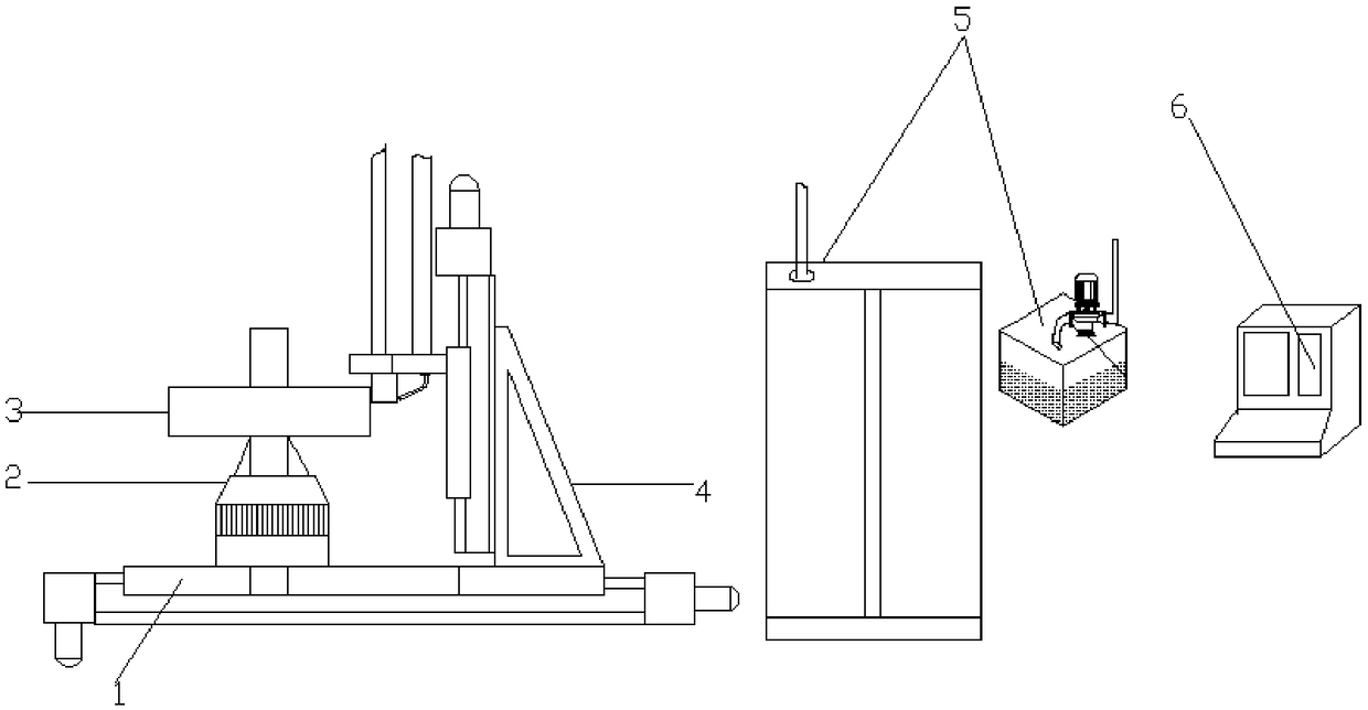
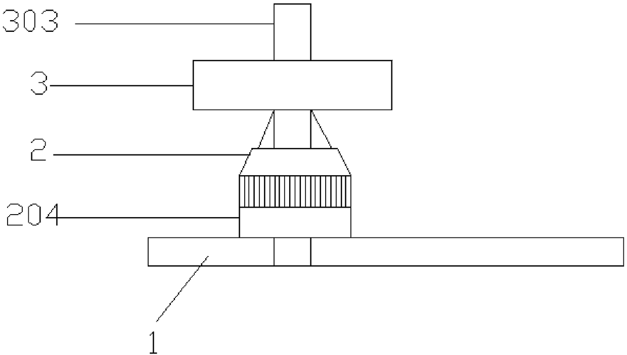
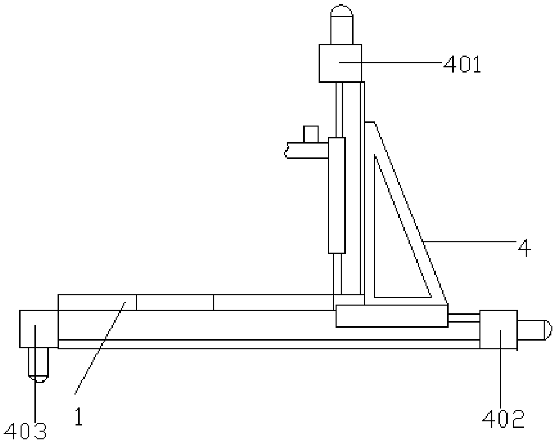
[0065] In actual use, the clamping and positioning device 2 fixes and clamps the shaft 303 of the gear 3 on the chuck 204 of the platform on the base 1, and the gear attitude adjustment system 4 adjusts the platform on the base 1, wherein the user respectively passes X The direction adjustment mechanism 402 or the Y direction adjustment mechanism 403 or the Z direction adjustment mechanism 401 adjusts the distance and gap between the induction heater 5011 and the gear teeth 301, and aligns the position of the induction heater 5011 with the position where the gear teeth 301 need to be quenched ( Gear tooth load surface 302), the controller uses the transformer 5012 to control the quenching equipment to quench the gear teeth 301 according to the quenching parameter requirements, and adjusts the induction frequency and voltage and current output parameters of the transformer 5012 or induction heater 5011 according to the quenching requirements. At the same time, The controller als...


PUM


Abstract

The invention discloses gear quenching equipment special for a hoisting forklift. The gear quenching equipment comprises a base, a clamping and positioning device, a gear posture-adjusting system, gear quenching equipment and a controller. The clamping and positioning device is located on the base and used for fixing and clamping a gear; the gear posture-adjusting system is connected with the clamping and positioning device and allows the posture of the gear to be adjusted in the X direction and the Y direction; the gear quenching equipment is connected with a Z-direction adjusting mechanism of the gear posture-adjusting system and quenches gear teeth of the gear unilaterally or nonuniformly; and the controller controls the clamping and positioning device to clamp the gear, or controls thegear posture-adjusting system to adjust the posture or controls the gear quenching equipment to operate. The controller is connected with a gear monitoring system used for monitoring the machining state of the gear in real time. The gear quenching equipment is high in intelligent degree, the gear quenching temperature and the gear quenching depth are controlled precisely, the quality of productsis improved significantly, and the yield of the products is increased significantly, the machined gear teeth are high in strength, good in abrasion resistance, long in service, and the bearing capacity is high.

Description

technical field [0001] The invention relates to the field of gear quenching, in particular to a special gear quenching equipment for lifting forklifts. Background technique [0002] As we all know, gears are key components in mechanical equipment, and they are widely used in industrial fields such as automobiles, airplanes, tanks, and ships. It has the advantages of accurate transmission, compact structure and long service life. Gear transmission is the most common mechanical vibration in modern machines, an important form of transmitting mechanical power and motion, and an important basic part of mechanical products. Compared with belt, chain, friction, hydraulic and other machinery, it has a series of advantages such as large power range, high transmission efficiency, high peripheral speed, accurate transmission ratio, long service life, and small size and structure. Therefore, it has become an indispensable transmission part for many mechanical products, and it is also ...

Claims


Application Information

Patent Timeline
IPC IPC(8): C21D9/32C21D1/10C21D1/667
CPCC21D1/10C21D1/667C21D9/32Y02P10/25
Inventor 周金和征茂德
Owner 苏州百搭王者物流技术有限公司
Why Eureka
Try Eureka