Drilling method for improving drilling accuracy of high-thickness-diameter PCB

A technology of PCB board and drilling method, which is used in the field of drilling to improve the drilling accuracy of high-thickness PCB boards, can solve the problem that the length of the drill cannot be infinitely lengthened, there is dislocation at the drill connection, and the printed board is scrapped by blasting holes, etc. problem, to achieve the effect of good quality in the hole, reducing scrap, and improving the yield of production quality

Inactive Publication Date: 2019-01-11
GUANGZHOU MEADVILLE ELECTRONICS
View PDF5 Cites 0 Cited by
  • Summary
  • Abstract
  • Description
  • Claims
  • Application Information

AI Technical Summary

Problems solved by technology

The disadvantages of the method of lengthening the drill are: 1. During the process of clamping the drill 2, the drill spindle 1 will inevitably produce an offset angle α (the angle between the spindle centerline 3 and the drill tip), when the drill 2 The longer the length, the greater the offset angle α, and the worse the drilling accuracy (the position of the angle between the drill spindle 1 and the drill 2 is as follows figure 1 ); 2. After the main shaft of the drilling rig clamps the drill bit, the drill bit will rotate at a high speed. During the high-speed rotation and drilling process, it will contact the aluminum sheet 4 and the printed board 5 successively. It touches the aluminum sheet 4 and the printed board 5 At this time, a large cutting force resistance will be generated, which will cause the drill bit 2 to shift, resulting in the deviation of the drill hole 6 (the longer the length of the drill bit, the greater the offset), and ev

Method used


Image

  • Drilling method for improving drilling accuracy of high-thickness-diameter PCB
  • Drilling method for improving drilling accuracy of high-thickness-diameter PCB
  • Drilling method for improving drilling accuracy of high-thickness-diameter PCB

Examples


Embodiment Construction

[0032] In the following, the present invention will be further described in conjunction with the drawings and specific implementations. It should be noted that, provided that there is no conflict, the following embodiments or technical features can be combined to form new embodiments. .

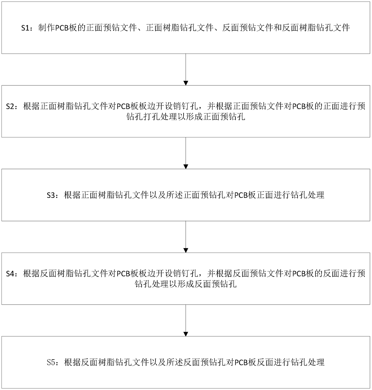
[0033] Such as figure 2 As shown, the present invention provides a drilling method for improving the drilling accuracy of a high-thickness PCB board, which includes the following steps:

[0034] S1: Make the front-side pre-drilling file, the front-side resin drilling file, the back-side pre-drilling file and the back-side resin drilling file of the PCB board;

[0035] In this step, the front resin drilling file includes the front side pin file and the graphic front file. The reverse resin drilling file includes a pin file on the reverse side of the board edge and a file on the reverse side of the figure. The pin file on the reverse side of the board edge is a mirror image file of the pin file on ...


PUM


Abstract

The invention discloses a drilling method for improving the drilling accuracy of a high-thickness-diameter PCB. The method comprises the following steps that a front side pre-drilling file, a front side resin drilling file, a reverse side pre-drilling file and a reverse side resin drilling file of the PCB are prepared; a pin hole is formed in the PCB edge according to the front resin drilling file, and the front side of the PCB is subjected to pre-drilling slotting process to form a front side pre-drilling hole according to the front pre-drilling file; the front side of PCB is subjected to drilling process according to the front side resin hole drilling file and the front side pre-drilling hole; a pin hole is formed in the PCB edge according to the reverse side resin drilling file, and thereverse side of the PCB is subjected to pre-drilling process to form a reverse side pre-drilling hole according to the reverse side pre-drilling file; and the reverse side of the PCB is subjected tothe drilling process according to the reverse side resin drilling file and the reverse side pre-drilling hole. A pre-drilling process is introduced, cutting force resistance produced in the resin drilling process is greatly reduced, and the yield of production quality is improved.

Description

Technical field [0001] The invention relates to a drilling technology, in particular to a drilling method for improving the drilling accuracy of a high-thickness PCB board. Background technique [0002] At present, with the rapid development of electronic products in the direction of miniaturization, high density, high integration and multi-function, the requirements for printed circuit boards are getting higher and higher, with high density, complex structure, and high Features such as layering, high thickness-to-diameter ratio, and small porosity In the current industry, the resin drilling process mainly includes two drilling methods: ordinary resin drilling and elongated drill vertical drilling. Among them, ordinary resin drilling is more common in the industry, and the length of ordinary drills is consistent with one-time drilling and printing. The condition of the board (general drill length-printed board thickness-aluminum sheet thickness (thickness is generally 0.2mm) ≥ 0...

Claims


Application Information

Patent Timeline
IPC IPC(8): B26F1/16B26D7/00
CPCB26D7/00B26F1/16
Inventor 刘勇
Owner GUANGZHOU MEADVILLE ELECTRONICS
Why Eureka
Try Eureka