Full-automatic spherical material perforating machine

A fully automatic, punching machine technology, used in boring/drilling, drilling/drilling equipment, applications, etc., can solve problems such as reduced work efficiency, slow feeding speed, and large safety hazards, and achieves high drilling efficiency. The effect of hole efficiency, high punching precision and high safety

Inactive Publication Date: 2016-04-13
山东云途信息科技有限公司
View PDF9 Cites 13 Cited by
  • Summary
  • Abstract
  • Description
  • Claims
  • Application Information

AI Technical Summary

Problems solved by technology

[0002] In the jewelry and jade processing industry, when drilling spherical materials, it is generally carried out by manual retrieving and clamping. Not only is the feeding speed slow, but it is also easy to hurt the operator, which poses a great safety hazard.
[0003] At the same time, the existing punching machine can only be carried out by manual loading and unloading, which cannot realize the batch punching process of spherical materials, and the punching machine can only drill from one direction, which is easy to produce holes after drilling. The burrs seriously affect the use and appearance. In the process of manual clamping, accurate positioning is often not possible. Most of the holes punched are not on the same axis, which reduces the appearance and neatness of spherical materials when they are made into necklaces. It not only increases labor intensity and production cost, but also reduces work efficiency
[0004] In addition, among the existing automatic feeding equipment, although there are automatic one-by-one feeding equipment, they are difficult to be used in the automatic feeding process of the jewelry and jade processing industry, and cannot realize the single separation and one-by-one feeding action of spherical materials

Method used


Image

  • Full-automatic spherical material perforating machine
  • Full-automatic spherical material perforating machine
  • Full-automatic spherical material perforating machine

Examples


Embodiment Construction

[0025] In order to facilitate the understanding of those skilled in the art, the present invention will be further described below in conjunction with the embodiments and accompanying drawings, and the contents mentioned in the embodiments are not intended to limit the present invention.

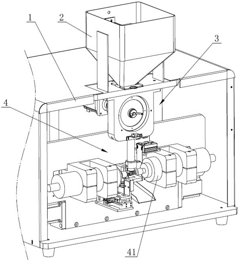
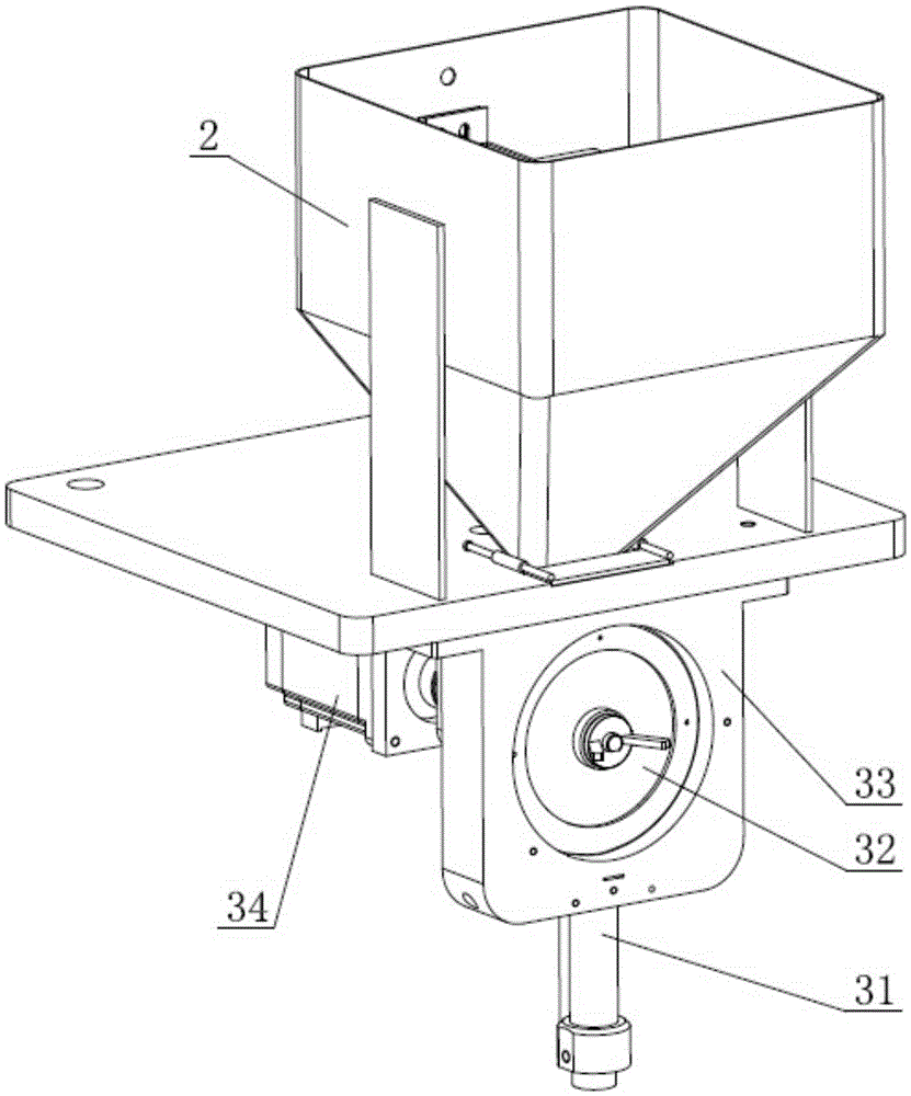
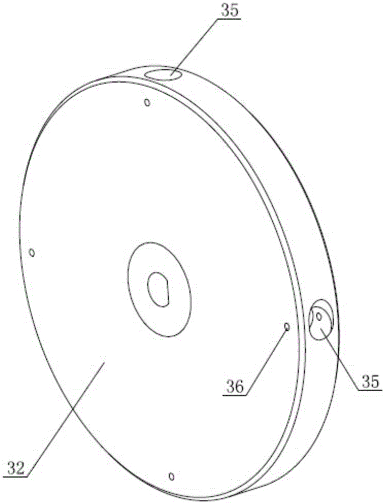
[0026] Such as Figure 1 to Figure 4 As shown, a fully automatic spherical material punching machine includes a frame 1 and a material storage part 2 installed on the frame 1, a material distribution component 3 and a punching component 4, and the material distribution component 3 includes a The spherical objects in the material storage part 2 are transported to the material pipe 31 of the punching assembly 4 one by one; The drill bit is on the same axis as the drill bit of another drilling device 41 .

[0027] In the practical application of the punching machine, the spherical materials are centrally stored in the material storage part 2, and enter the material distribution assembly 3 unde...


PUM


Abstract

The invention relates to the technical field of automatic feeding devices and in particular relates to a full-automatic spherical material perforating machine comprising a rack, and a storing part, a distribution assembly and a perforating assembly which are arranged on the rack. The full-automatic spherical material perforating machine is characterized in that the distribution assembly comprises a material pipe for conveying spherical materials in the storing part to the perforating assembly one by one; the perforating assembly comprises a clamp, and two drilling devices which are positioned at two sides of the clamp; the drill of one drilling device and the drill of the other drilling device are in the same axis. The full-automatic spherical material perforating machine can be used for achieving full-automatic batch perforating processing of the spherical materials, so that the perforating efficiency of the spherical materials is greatly improved; the perforating precision is high; the double-direction perforating can be performed once; no burr is generated; the manual contact of the materials in the perforating process is avoided; the safety is relatively high; the practicability is high.

Description

technical field [0001] The invention relates to the technical field of automatic feeding equipment, in particular to a fully automatic spherical material punching machine. Background technique [0002] In the jewelry and jade processing industry, when drilling spherical materials, it is generally carried out by manual retrieving and clamping. Not only the feeding speed is slow, but also it is easy to hurt the operator, which poses a great safety hazard. [0003] At the same time, the existing punching machine can only be carried out by manual loading and unloading, which cannot realize the batch punching process of spherical materials, and the punching machine can only drill from one direction, which is easy to produce holes after drilling. The burrs seriously affect the use and appearance. In the process of manual clamping, accurate positioning is often not possible. Most of the holes punched are not on the same axis, which reduces the appearance and neatness of spherical m...

Claims


Application Information

Patent Timeline
Patent Type & Authority Applications(China)
IPC IPC(8): A44C27/00B28D5/02B23B39/16
CPCA44C27/001B23B39/16B28D5/021
Inventor 张斌
Owner 山东云途信息科技有限公司
Why Eureka
Try Eureka