Corrugated skins for aircraft and methods of their manufacture

An aircraft and shell technology, applied in the field of aircraft shells, can solve problems such as inappropriateness, and achieve the effect of reducing weight

Inactive Publication Date: 2010-06-09
GE AVIATION SYST LTD
View PDF6 Cites 9 Cited by
  • Summary
  • Abstract
  • Description
  • Claims
  • Application Information

AI Technical Summary

Problems solved by technology

This material is provided to increase the strength and stiffness of the airfoil but is not suitable to allow any significant structural movement to occur

Method used


Image

  • Corrugated skins for aircraft and methods of their manufacture
  • Corrugated skins for aircraft and methods of their manufacture
  • Corrugated skins for aircraft and methods of their manufacture

Examples


Embodiment Construction

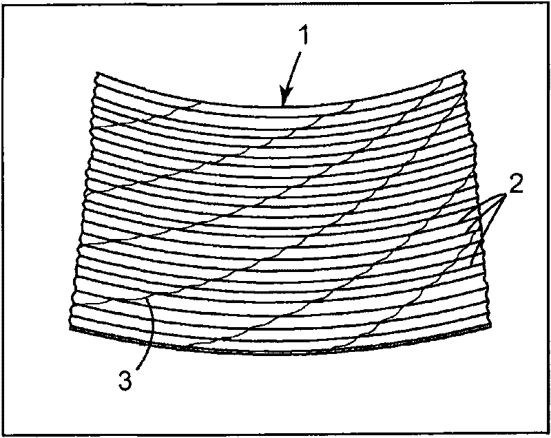
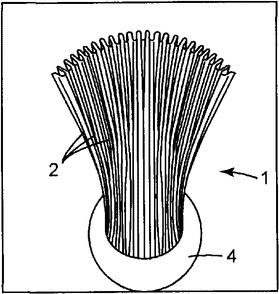
[0022] figure 1 is a schematic perspective view of a corrugated shell region 1 with a series of corrugations 2 . The casing (skin) 1 is formed using a substrate material impregnated with a curable resin, and after the molding process, the casing is cured to harden the resin. The resin-impregnated substrate material is applied to the flexible corrugated mold by forming a flexible corrugated mold (not shown) using a master tool, and is applied to the flexible corrugated mold by applying it to a bending rigid forming machine (not shown). ) to shape the mold and the substrate material on it, so that the substrate material can be formed.

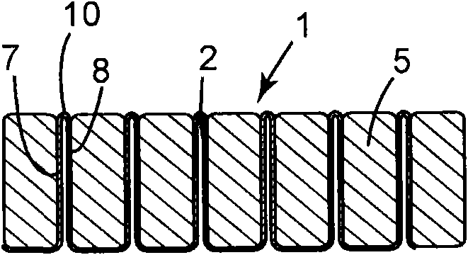
[0023] Specifically, the flexible corrugated mold was made by applying silicone rubber to a standard tool comprising a corrugated rigid mold without any curvature. Once the silicone rubber has been cast, the finished flexible rubber mold is removed from the standard tool. A layer of backing material, optionally covered with fluorinated ethylen...


PUM


Abstract

A skin (1) for a morphing structure of an aircraft is disclosed, said skin comprising one or more corrugations (2). A corresponding method of manufacturing a skin for a morphing structure of an aircraft is also disclosed comprising shaping the skin (1) to a desired form including one or more corrugations (2). In one embodiment, Aluminium forming bars (5) are sequentially introduced between folds (7, 8) in the material of the skin.

Description

technical field [0001] The invention relates to skins for aircraft, in particular for wings or fuselages thereof. Background technique [0002] Gradient structures are gradually being used in aircraft, whether they are unmanned aerial vehicles (UAVs) or larger vehicles. This structure required a shell that would conform to the movement imposed by the graded structure. Traditional materials used to make aircraft skins, such as aluminum sheets, cannot fully recover from strains above low levels (less than 1% for most metals). Rubber materials are known for their ability to recover from high strains, but have very limited strength and stiffness. [0003] The use of corrugated materials in conventional aircraft wing structures is known. This material is provided to increase the strength and stiffness of the airfoil, but is not suitable to allow any significant structural movement to occur. Furthermore, these skins are generally only intended to supplement the strength and st...

Claims


Application Information

Patent Timeline
Patent Type & Authority Applications(China)
IPC IPC(8): B64C1/00
CPCB64C3/26Y02T50/43Y02T50/433B64C3/48B64C1/12Y02T50/40B29C35/02B29C43/18B29C43/20B29C70/30B29C70/34B29C70/40B29C70/42B29C70/46B64C3/52
Inventor K·D·波特
Owner GE AVIATION SYST LTD
Why Eureka
Try Eureka