Feeding device of pouring pile underwater concrete and pouring method thereof

A technology of underwater concrete and pouring method, which is applied in the direction of construction and infrastructure engineering, etc., can solve the problem of limited reduction of resistance pressure, achieve the effect of increasing active pressure, significant economic and comprehensive benefits, and accelerated pouring speed

Inactive Publication Date: 2010-06-09
DALIAN AERBIN GROUP
View PDF0 Cites 12 Cited by
  • Summary
  • Abstract
  • Description
  • Claims
  • Application Information

AI Technical Summary

Problems solved by technology

[0004]In the field of building construction, in the process of pouring concrete in cast-in-situ piles, when the conduit is blocked, the traditional method is to lift the conduit to reduce the burial of the conduit end in the pile. Deep, so as to reduce the resistance force of the concrete in the pile and the mud retaining wall to the concrete in the conduit, but it is restricted by the lifting height of the conduit (the maximum value of the conduit lifting must be 300mm less than the depth of the concrete embedded in the pile at the end of the conduit), the reduction of this resistance force The amount is very limited, and the purpose of the present invention is to make the increase of the concrete self-weight pressure in the conduit not limited by the depth of the lower end of the conduit embedded in the concrete, and to increase it to a greater extent, so as to effectively solve the problem of conduit blockage

Method used


Image

  • Feeding device of pouring pile underwater concrete and pouring method thereof
  • Feeding device of pouring pile underwater concrete and pouring method thereof
  • Feeding device of pouring pile underwater concrete and pouring method thereof

Examples


Embodiment Construction

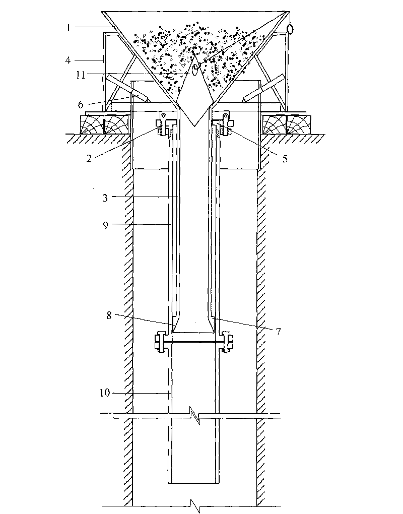
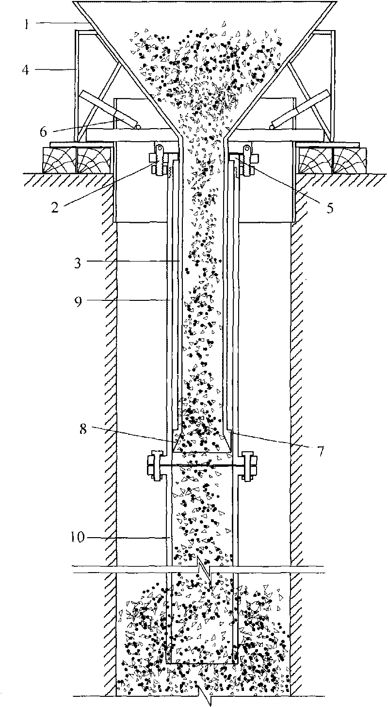
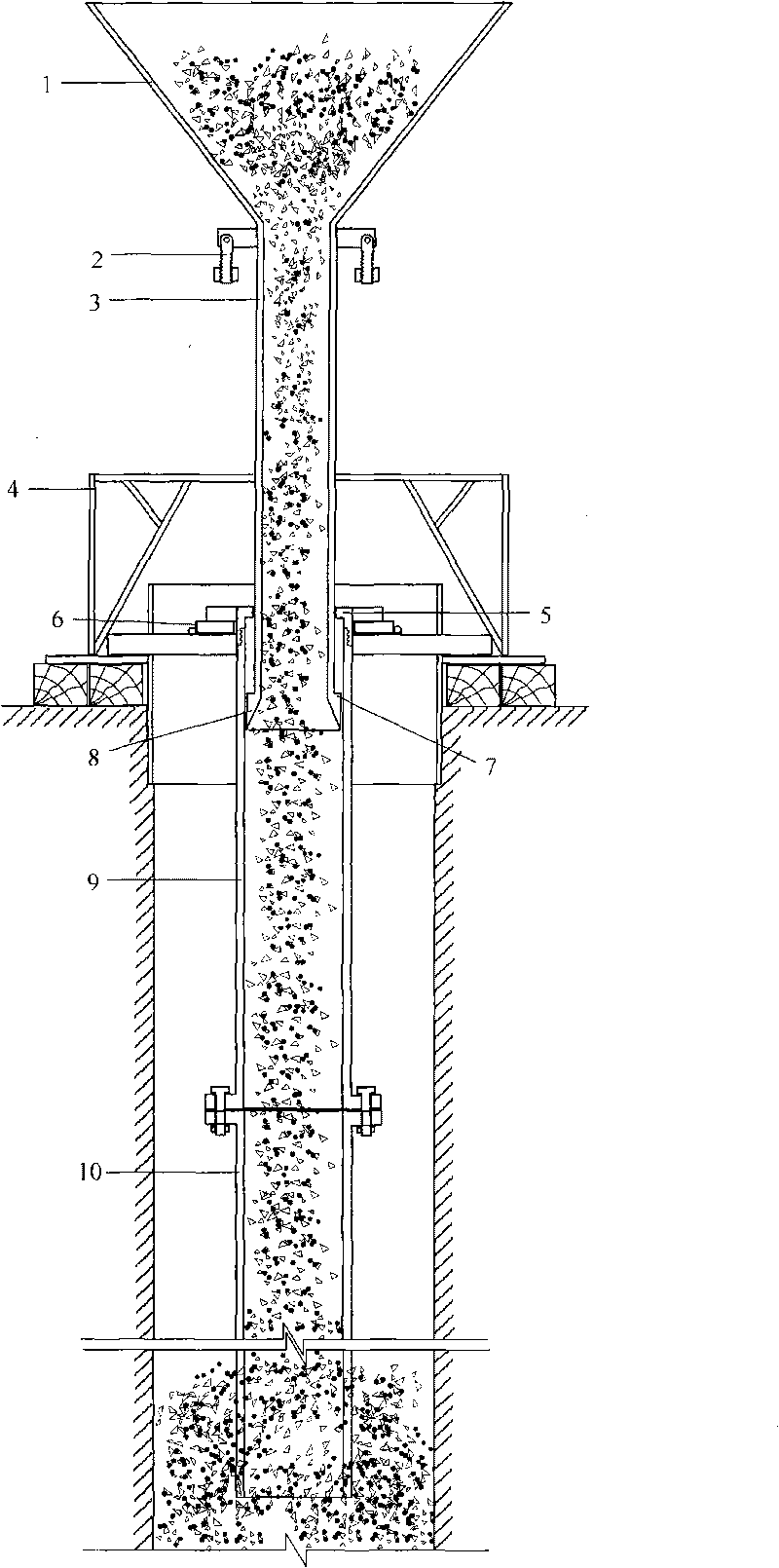
[0027] The present invention will be further described below in conjunction with the accompanying drawings.

[0028] Depend on Figure 1-9 It can be seen that, at the pile hole after the hole is formed, install the hopper frame 4 and the card cover 6, open the card cover 6, and then connect the circular conduit 10 joint by joint, pass the card cover 6, and go down into the pile hole from the bottom of the hole. At the position of 300mm-500mm, the top of the circular conduit 10 is connected to the flange at the lower end of the casing 9, and then the hopper 1 is placed on the hopper frame 4, and the hopper 1 is connected to the casing 9 by tightening the bolt 2; 11 Plug the feed inlet at the bottom of hopper 1, and fill the hopper 1 with an appropriate amount of concrete according to the pre-calculated results [the amount of filling shall not be less than: 3.14×radius of cast-in-place pile 2 ×(the distance between the bottom end of the conduit and the bottom of the hole+0.8m)]...


PUM


Abstract

The invention belongs to the field of building construction, in particular to a feeding device of pouring pile underwater concrete and a pouring method thereof. The device comprises a hopper, a hopper frame, a sleeve pipe, a guide pipe and a hopper plug. The feeding device is characterized in that the lower end of the hopper is provided with the lining guide pipe; fixed bolts are arranged outside a lower port of the hopper; the upper end of the sleeve pipe is provided with a seal cap; bolt grooves are arranged outside the seal cap and respectively correspond to the fixed bolts outside the hopper in position; two folio valves are arranged on a clamping cover and sleeved at the lower port of the outer edge of the seal cap during working; the sleeve pipe is connected with the guide pipe by a flange; and the hopper plug is an iron plug of which both ends are in cone shapes. Compared with the traditional method for reducing the resistance of concrete in a pile and the slurry protecting wall on the concrete in the guide pipe just by lifting the guide pipe in a limited way, the invention greatly improves the active pressure of pouring concrete in the guide pipe, effectively solves the problem of difficult falling of the concrete, improves the pouring speed, ensures the molded pile quality and has obvious economic and comprehensive benefits.

Description

Technical field: [0001] The invention belongs to the field of building construction, and in particular relates to a feeding device and pouring method for underwater concrete of cast-in-place piles. technical background: [0002] In the field of building construction, when the pouring of cast-in-situ pile concrete adopts the underwater concrete pouring technology, during the pouring process, due to the continuous mixing of soil on the wall of the pile hole into the mud retaining wall, the proportion of the mud retaining wall continues to increase, and the end of the conduit is buried The length of the concrete continues to increase. When the resistance pressure generated by the concrete in the pile and the mud retaining wall is greater than the pressure of the concrete's own weight in the conduit, the concrete in the conduit cannot fall, causing the conduit to be blocked. [0003] To solve this problem, a solution often used in the construction process is to reduce the buried...

Claims


Application Information

Patent Timeline
Patent Type & Authority Applications(China)
IPC IPC(8): E02D15/06
Inventor 魏勇刘显全
Owner DALIAN AERBIN GROUP
Why Eureka
Try Eureka