Hinge structure

A hinge structure and limiter technology, which is applied to the structural parts of portable computers, instruments, electrical digital data processing and other directions, can solve the problems of the limit protrusion 122 being easily broken, affecting the rotation angle range, and poor impact resistance, etc. Achieve the effect of saving assembly space, good impact resistance, and high breaking strength

Inactive Publication Date: 2010-06-09
HONG FU JIN PRECISION IND (SHENZHEN) CO LTD +1
View PDF0 Cites 3 Cited by
  • Summary
  • Abstract
  • Description
  • Claims
  • Application Information

AI Technical Summary

Problems solved by technology

[0007] However, the hinge structure 10 realizes the position-limiting function by cooperating the position-limiting projection 122 on the fixing part 12 with the position-limiting notch 142 on the position-limiting part 14. The position-limiting protrusion 122 protrudes out of the fixed bracket 12, When the end of the position notch 142 is in contact with the position-limiting protrusion 122, the joint between the position-limiting protrusion 122 and the fixed bracket 12 is prone to stress concentration, which makes the position-limiting protrusion 122 easy to break and has poor impact resistance, thus affecting the rotation. The rotation angle range of support 13 relative to fixed support 12
Therefore, the limiting effect of the hinge structure 10 is relatively poor.
In addition, the hinge structure 10 adopts the limiting member 14 and the rotating positioning member 16 to realize the limiting and positioning functions, and the manufacturing cost is high due to many parts.

Method used


Image

  • Hinge structure
  • Hinge structure
  • Hinge structure

Examples


Embodiment Construction

[0020] The hinge structure of the present invention will be further described in detail with reference to the accompanying drawings and preferred embodiments.

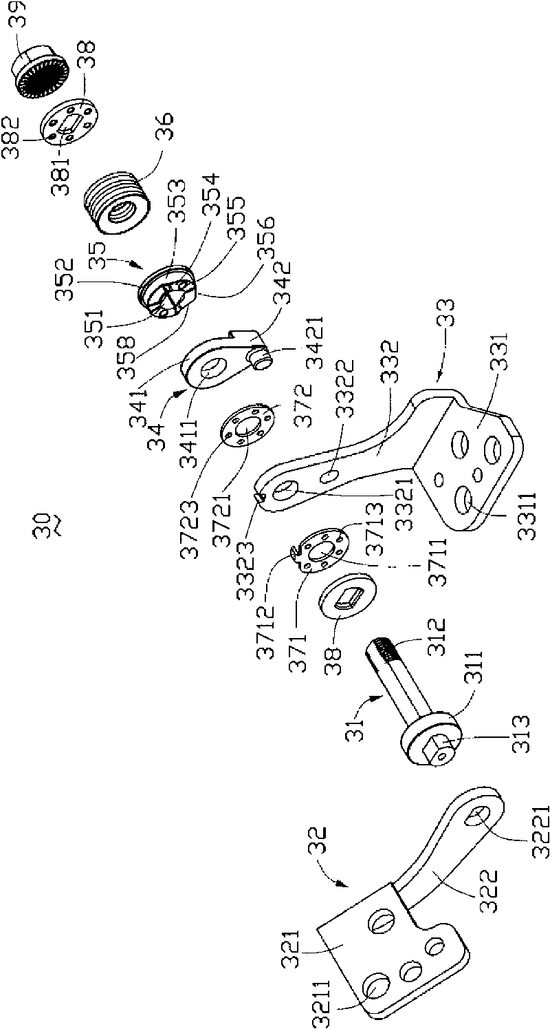
[0021] See also Figure 2 to Figure 4 , the hinge structure 30 of the present invention includes a pivot 31, a rotating bracket 32, a fixed bracket 33, a fixing piece 34, a limit piece 35, an elastic piece 36, a first friction plate 371, a second friction plate A piece 372, two gaskets 38 and a locking piece 39.

[0022] The pivot 31 has a non-circular cross-section, a disc-shaped flange 311 is formed at one end, and a threaded portion 312 is formed at the other end. One end of the pivot 31 forming the flange 311 further protrudes out of the flange 311 to form an inserting portion 313 .

[0023] The rotating bracket 32 ​​includes a base plate 321 on which a plurality of fixing holes 3211 are defined. An arc-shaped positioning plate 322 extends from one side of the base plate 321 , and an end of the arc-shaped positi...


PUM


Abstract

The invention provides a hinge structure. The hinge structure comprises a pivot shaft, a rotating bracket, a fixed bracket, a fixing element and a limiting member, wherein the rotating bracket and the limiting member are connected with the pivot shaft in a non-rotating way; the fixed bracket and the fixing element are rotatably connected with the pivot shaft; the fixing member is fixedly connected with the fixed bracket; the fixing element is provided with a limiting step; a limiting surface fitting the limiting step is formed on the circumference of the limiting member; and one of the fixing element and the limiting member is provided with a positioning bump while the other is correspondingly provided with a positioning groove fitting the positioning bump. The limiting member includes a column body of which the periphery projects outwards and forms a limiting surface and an adjacent surface, wherein the limiting surface and the adjacent surface are all planes, one ends of the limiting surface and the adjacent surface are connected to each other through an outer periphery surface of a small segment of the column body, and the other ends of the limiting surface and the adjacent surface are respectively transited with the periphery of the column body in an arc state. The hinge structure has the beneficial effects of good limiting effect and low manufacturing cost.

Description

technical field [0001] The invention relates to a hinge structure, in particular to a hinge structure for an electronic device. Background technique [0002] Electronic devices such as notebook computers generally include a body and a cover. The display screen is disposed on the cover. In order to make the display screen have a better viewing angle, it is usually necessary to rotatably connect the cover to the body through a hinge structure. [0003] see figure 1 A hinge structure 10 includes a pivot 11 , a fixed bracket 12 , a rotating bracket 13 , a limiting member 14 , a fixing member 15 , a rotating positioning member 16 , a shrapnel set 17 and a nut 18 . [0004] The pivot 11 has a non-circular cross section, a flange 111 is formed at one end, and a threaded portion 112 is formed at the other end. A circular pivot hole 121 through which the pivot shaft 11 passes is opened on the fixing bracket 12 , and a limiting protrusion 122 is formed near the pivot hole 121 . The...

Claims


Application Information

Patent Timeline
Patent Type & Authority Applications(China)
IPC IPC(8): F16C11/10H05K5/03
CPCG06F1/1616G06F1/1681
Inventor 李小波王金鑫李坚
Owner HONG FU JIN PRECISION IND (SHENZHEN) CO LTD
Why Eureka
Try Eureka