Device for measurement and conversion of voltage signal

A conversion device and voltage signal technology, applied in the direction of using digital measurement technology for measurement, electronic circuit testing, etc., can solve problems such as the inability to meet the requirements of microvolt-level precision measurement, and achieve the effect of accurate measurement and improved voltage measurement accuracy

Inactive Publication Date: 2011-11-02
西安明泰半导体科技有限公司
View PDF0 Cites 0 Cited by
  • Summary
  • Abstract
  • Description
  • Claims
  • Application Information

AI Technical Summary

Problems solved by technology

Therefore, even without the introduction of long leads, the above two cases cannot meet the measurement requirements of microvolt level accuracy in the test

Method used


Image

  • Device for measurement and conversion of voltage signal
  • Device for measurement and conversion of voltage signal
  • Device for measurement and conversion of voltage signal

Examples


Embodiment

[0023] If the expected value of the output reference voltage of the chip to be tested is 5.0V±0.1%, that is, the output of a good product should be 4.995V-5.005V, only in the range of ±5mV. If the tester is used to test directly, the test accuracy of the tester is ±1mV, so there will be a great possibility of manslaughter and misplacement. If you consider the impact of long leads, the situation will be even more serious.

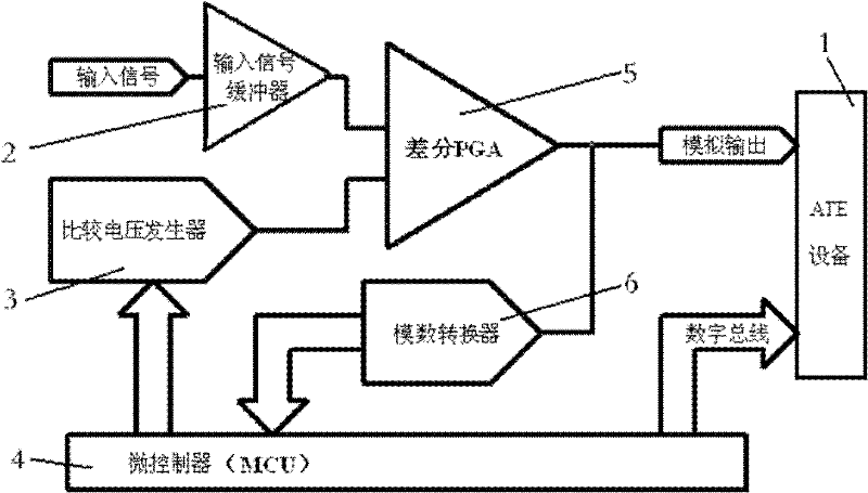
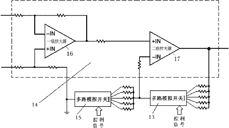
[0024] refer to Figure 5 , before using this device for testing, first select the DIP switch I 8 as the digital ATE interface with ATE equipment 1, that is, the digital ATE mode. After the device is powered on, the microcontroller 4 first checks the setting of the DIP switch I 8 Interface mode (in this example, digital ATE mode). During testing, ATE passes the device's I 2 The comparison voltage of the C communication port is 5.0V, and the magnification is set to 1000 times. The multi-channel analog switch I 13 and the multi-channel analog switch II 15 ...


PUM


Abstract

The invention discloses a device for measurement and conversion of a voltage signal, comprising a difference PGA, the difference PGA is respectively connected with an input signal buffer and a comparison voltage generator, the comparison voltage generator is connected with a microcontroller, one output end of the difference PGA is connected with the microcontroller by a analog to digital converter, the input signal buffer, the comparison voltage generator, the microcontroller, the difference PGA and the analog to digital converter are respectively power-supplied by a power module, and the other output end of the difference PGA is connected with ATE equipment, the microcontroller is connected with the ATE equipment by a digital bus, and the comparison voltage generator is composed of the analog to digital converter and a voltage follower which are connected; the device can lead an integration circuit ATE system to measure a microvolt level signal accurately under a condition of a long lead wire.

Description

technical field [0001] The invention belongs to the technical field of integrated circuit test and measurement, and relates to a measurement and conversion device for voltage signals. Background technique [0002] In integrated circuit automated test equipment (ATE equipment), especially for the final test of integrated circuits, due to the relationship between the size and shape of the manipulator (Handler) and ATE, it is impossible to connect the device under test (DUT) to the ATE mid-board The source / meter is directly connected, so a long lead wire must be used to connect the DUT to the ATE. The length of the lead wire is as short as 1-2 meters, and the length of the lead wire can reach 5 meters. Due to the introduction of long lead wires, lead wire errors are inevitably brought about and the interference of the external electromagnetic field on the signal to be tested is aggravated. Although the Kelvin wiring and electromagnetic shielding methods used in ATE can reduce ...

Claims


Application Information

Patent Timeline
Patent Type & Authority Patents(China)
IPC IPC(8): G01R19/25G01R31/28
Inventor 刘义芳
Owner 西安明泰半导体科技有限公司
Why Eureka
Try Eureka