
A Broadband Voltage Transformer

A voltage transformer and broadband technology, applied in the field of broadband voltage transformers, can solve the problems of low voltage measurement accuracy, low primary insulation reliability, and inability to realize accurate measurement of broadband voltage signals, so as to achieve high primary insulation reliability and broaden the use Effect of temperature range and temperature rise reduction

Active Publication Date: 2022-01-18
GLOBAL ENERGY INTERCONNECTION RES INST CO LTD +1
View PDF0 Cites 0 Cited by
  • Summary
  • Abstract
  • Description
  • Claims
  • Application Information

AI Technical Summary

Problems solved by technology

[0017] In order to overcome the shortcomings of low primary insulation reliability, low voltage measurement accuracy and inability to realize accurate measurement of broadband voltage signals in the above-mentioned prior art, the present invention provides a broadband voltage transformer, including hollow insulators, metal flanges, and fixed flanges. , resistance-capacity equalizing components, resistance-capacity hybrid voltage divider, base and signal acquisition module; metal flanges are installed at both ends of the hollow insulator, the metal flange at the top of the hollow insulator is connected to the primary system, and the metal flange at the bottom of the hollow insulator The flange is connected to the base; the inner wall of the metal flange is installed with a fixed flange, and the two ends of the resistance-capacity equalizing component are respectively connected to the fixed flange; the top of the resistance-capacity hybrid voltage divider is connected to the primary system, and its bottom is connected to the signal acquisition module

Method used


Image

  • A Broadband Voltage Transformer
  • A Broadband Voltage Transformer
  • A Broadband Voltage Transformer

Examples


Embodiment Construction

[0067] The present invention will be described in further detail below in conjunction with the accompanying drawings.

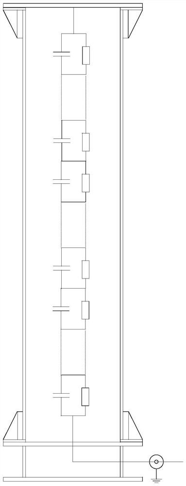
[0068] The embodiment of the present invention provides a broadband voltage transformer, its specific structure diagram is as follows Figure 5 As shown, it includes a hollow insulator 2, a metal flange 1, a fixed flange 4, a resistance-capacity equalizing component, a resistance-capacity hybrid voltage divider 5, a base 7 and a signal acquisition module 8;

[0069] The metal flange 1 is installed at both ends of the hollow insulator 2, the metal flange at the top of the hollow insulator 2 is connected to the primary system, the metal flange at the bottom of the hollow insulator 2 is connected to the base 7; the inner wall of the metal flange 1 is installed with a fixed flange 4, Both ends of the resistance-capacitance equalizing component are respectively connected to the fixed flange 4; both ends of the resistance-capacity hybrid voltage divider 5 are respe...


PUM


Abstract

The invention provides a broadband voltage transformer, which includes a hollow insulator, a metal flange, a fixed flange, a resistance-capacity equalizing component, a resistance-capacity hybrid voltage divider, a base and a signal acquisition module; metal flanges are installed at both ends of the hollow insulator , the metal flange at the top of the hollow insulator is connected to the primary system, and the metal flange at the bottom is connected to the base; the inner wall of the metal flange is equipped with a fixed flange, and the two ends of the resistance-capacity and pressure equalization component are connected to the fixed flange respectively; The top of the voltage divider is connected to the primary system, and its bottom is connected to the signal acquisition module. The broadband voltage transformer has high primary insulation reliability and high voltage measurement accuracy, and can realize accurate measurement of broadband voltage signals. The broadband voltage transformer provided by the present invention is suitable for both AC system and DC system, and has a wide range of applications. The specific application range covers DC transmission projects, AC transmission / distribution projects, high-speed railway power grids and any Areas and occasions where measurement needs are required.

Description

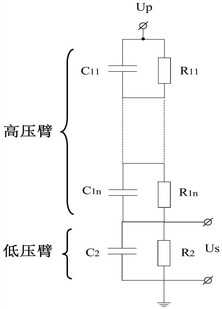
technical field [0001] The invention relates to the technical field of power systems, in particular to a high-precision, fast-response, high-reliability broadband voltage transformer free from on-site verification. Background technique [0002] The DC voltage transformer is an indispensable main equipment in the DC transmission system, which plays an important role in electric energy metering, power monitoring, and relay protection signal transmission. The DC voltage transformer in the prior art is composed of a resistor divider composed of a series of resistor elements connected in series. In order to prevent the resistor divider from being affected by various transient overvoltages (including lightning overvoltage), usually in the resistor A voltage equalizing capacitor is connected in parallel on the voltage divider. The specific schematic diagram of DC voltage transformer is as follows: figure 1 shown. Depending on the voltage level, the stages of the resistive divide...

Claims


Application Information

Patent Timeline
Patent Type & Authority Patents(China)
IPC IPC(8): H01F38/26G01R15/18
CPCH01F38/26G01R15/18
Inventor 董巍庞辉高冲周建辉
Owner GLOBAL ENERGY INTERCONNECTION RES INST CO LTD
Learn More