

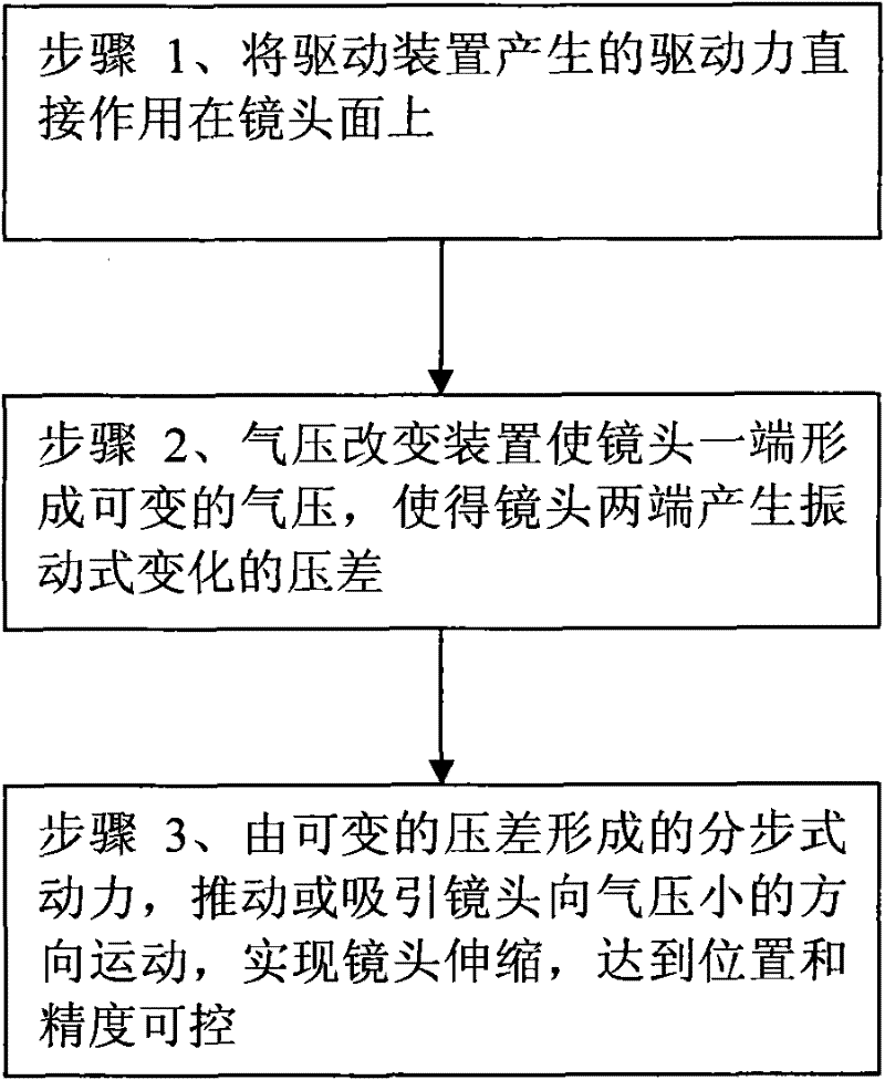
Driving method of zoomer lens device
A driving method and telescopic technology, applied in installation, optics, instruments, etc., can solve the problems of lens control and positioning, and achieve the effects of reduced power consumption, simple structure, and clear images
- Summary
- Abstract
- Description
- Claims
- Application Information
AI Technical Summary
Problems solved by technology
Method used
Image

Examples
Embodiment 1
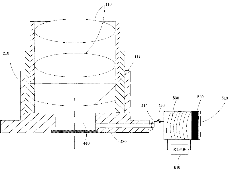
[0024] like figure 2 Shown is a specific embodiment of the retractable lens and the driving device. The lens device includes a retractable lens barrel 210, which is provided with at least two (or more) retractable lens groups 110 and 111 whose relative motion conforms to the rules of the zoom lens. In addition, the figure 2 Chips and printed circuit boards in the lens assembly are not shown. Wherein, the relative movement among several lenses in the lens group 110 (that is, between the lenses belonging to the lens group 110 ) also complies with the rules of zoom lenses. Wherein, the lens barrel 210, the contact surface between the retractable lens group 110 and the lens group 111 is a surface with a certain friction coefficient, which can make the retractable lens group use friction force to carry out the process after the extension or retraction is completed. The positioning is fixed. Further, a cavity 440 is formed between the lens surface of the retractable lens group ...
Embodiment 2
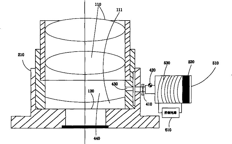
[0039] like image 3 Shown is another specific embodiment of the retractable lens and the driving device. The structure of this embodiment 2 is basically the same as that of the above-mentioned embodiment 1, the only difference is that in this embodiment, the cavity 440 in the lens is arranged between the adjacent lens surfaces of the lens group 110 and the lens group 111, and it passes through the through hole 430 is connected with the air pump 510 of the driving device. According to the setting position of the cavity 440 in this embodiment, the precise extension and retraction of the lens group 110 can be realized, so that the position and accuracy of the lens during the telescopic process can be controlled, and the optical zoom and automatic focus of the lens can be realized.
[0040] The method of the present invention also has another preferred embodiment, which can be combined with the above-mentioned embodiment 1 and embodiment 2, and two cavities can be set in the len...
Embodiment 3
[0042] like Figure 4 Shown is yet another specific embodiment of the retractable lens and the driving device. The structure of this embodiment 3 is basically the same as that of the above-mentioned embodiment 2, the only difference is that the driving device in this embodiment is also provided with a gas storage device 710 between the through hole 430 and the first valve 410, the gas storage device 710 For storing a certain amount of high-pressure gas, it may be a gas tank, which also includes a valve (not shown) arranged between the through hole 430 and the gas storage device 710 .
[0043] When the magnet 520 in the air pump 510 is under the control of the control circuit 610 to make a vibratory alternating movement towards the first valve 410, that is, towards the gas storage device 710, the control circuit 610 simultaneously controls the gas The valve of the storage device 710 is opened, and the gas in the gas storage device 710 is pressed into the cavity 440 because the...
PUM
 Abstract
Description
Claims
Application Information