Optical unit with shake correcting function

A shake correction, optical unit technology, applied in the direction of optical components, optical, electrical components, etc., can solve the problems of limited configuration space, difficult to obtain driving force, etc., and achieve the effect of easy assembly, good vibration resistance, and good responsiveness

Inactive Publication Date: 2014-02-26
SANKYO SEIKI MFG CO LTD
View PDF7 Cites 2 Cited by
  • Summary
  • Abstract
  • Description
  • Claims
  • Application Information

AI Technical Summary

Problems solved by technology

However, when the imaging optical unit is miniaturized and thinned, the arrangement space of the driving coil and the driving magnet for swinging the movable part on which the lens and the imaging element are mounted is limited, so it is difficult to obtain a sufficient space for the imaging unit. Driving force for swinging the movable part

Method used


Image

  • Optical unit with shake correcting function
  • Optical unit with shake correcting function
  • Optical unit with shake correcting function

Examples


Embodiment approach

[0221] (Structure of the magnetic drive mechanism for hand shake correction)

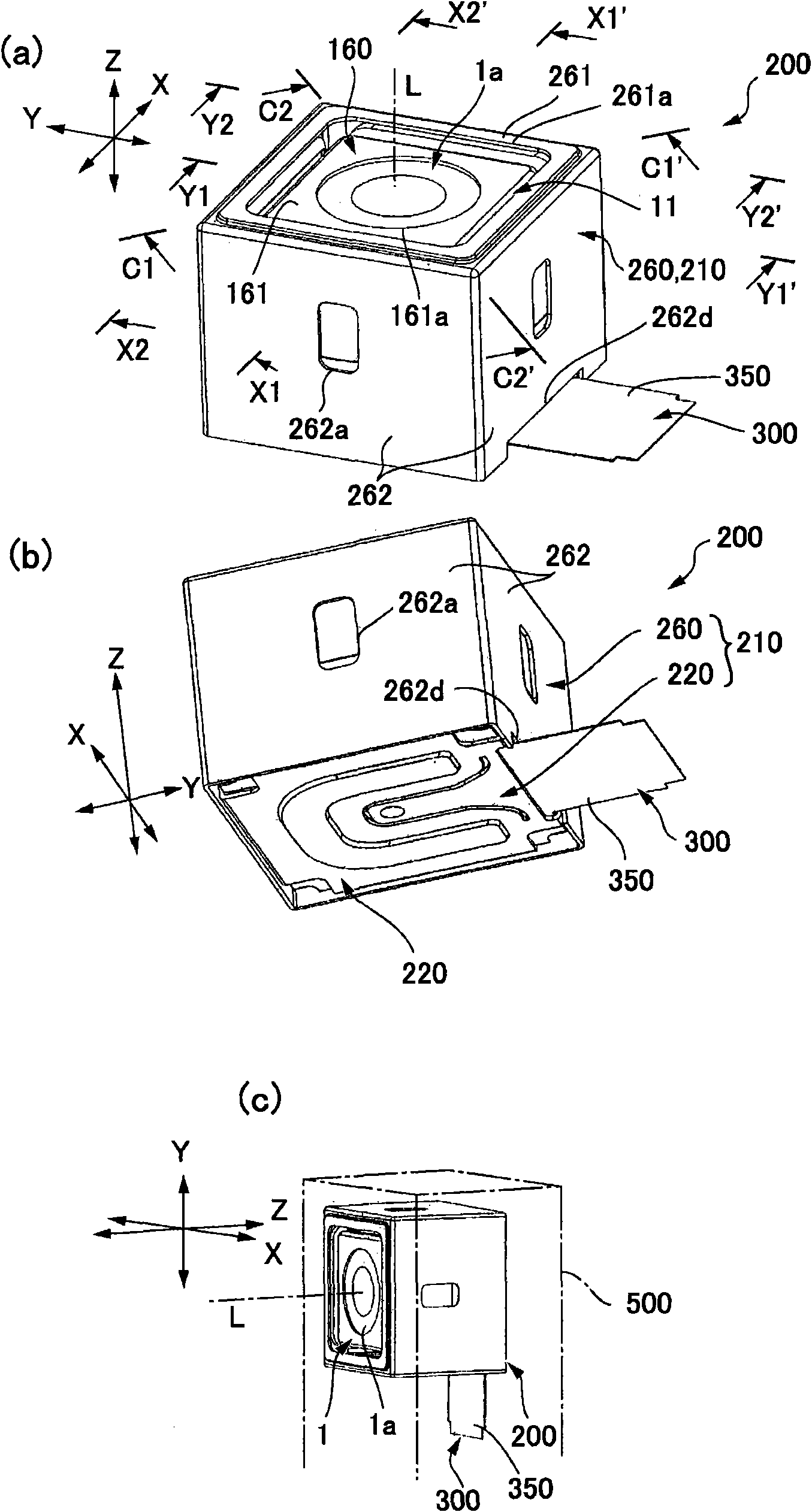
[0222] In the above-mentioned embodiments, a structure is adopted in which either of the first hand-shake correction magnetic drive mechanism 250x and the second hand-shake correction magnetic drive mechanism 250y is located on the side of the movable body, that is, the movable module One side holds shake correction coils (shake correction coils 230x, 230y), and the fixed body 210 side holds shake correction magnets (shake correction magnets 240x, 240y). However, it is also possible to employ a structure in which one of the first hand-shake correction magnetic drive mechanisms 250x and the second hand-shake correction magnetic drive mechanism 250y is movable on the side of the movable body. The hand shake correction coil is held on the module 1 side, the hand shake correction magnet is held on the fixed body 210 side, and the other hand shake correction magnetic drive mechanism is held on the movabl...

other Embodiment approach

[0332] The above-mentioned embodiment is an example of a more preferable aspect of the present invention, but is not limited thereto, and the present invention can be variously modified and implemented within the scope without changing the gist of the present invention.

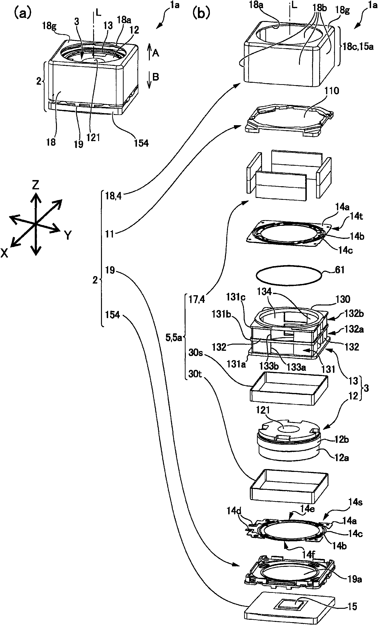
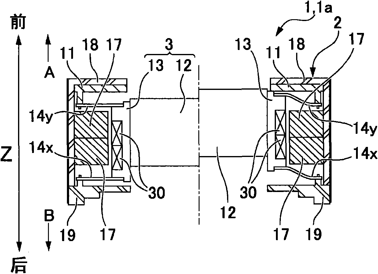
[0333] In the above-described embodiment, the shake correction magnet 21 is attached to the cover member 9 , and the shake correction coil 23 is attached to the housing 116 . Alternatively, for example, the shake correction magnet 21 may be attached to the casing 116 and the shake correction coil 23 may be attached to the cover member 9 . In this case, the center CL3 of the shake correction coil 23 is arranged below the contact surface 27 of the shake correction stone 21 . That is, the center CL3 of the shake correction coil 23 is arranged at a position closer to the fulcrum portion 119 than the magnetic force center of the shake correction magnet 21 in the optical axis direction.

[0334] Specifically, the ...


PUM


Abstract

The present invention may advantageously provide an optical unit with shake correcting function in which shake of a movable module is corrected with a small torque and a quick response without mechanically connecting the fixed body and the movable module through a drive mechanism. An optical unit with shake correcting function may include a movable module having a lens, a fixed body supporting the movable module, a shake detection sensor for detecting shake of the movable module, and at least one pair of magnetic drive mechanism for shake correction which is structured on both sides of the movable module so that the movable module is swung with respect to the fixed body on the basis of detection result of the shake detection sensor to correct the shake of the movable module. The magnetic drive mechanism for shake correction is disposed so that a shake correction magnet is held by the fixed body and a shake correction coil is held by the movable module.

Description

technical field [0001] The present invention relates to an optical unit with a shake correction function that corrects shake such as hand shake by swinging a module on which a lens is mounted. Background technique [0002] In optical devices such as photographing optical devices installed in mobile phones and digital cameras, laser pointers, portable and in-vehicle projection display devices, etc., when hand shake and external vibration are transmitted, the optical axis tends to shake. [0003] Therefore, for a photographing optical unit used in a portable photographing optical device, etc., a technique has been proposed in which the movable module is supported on a fixed body through an elastic body, and the side surfaces of the movable module are configured to utilize pressure. The actuator of the electric element corrects the hand shake by swinging the movable module around the X-axis and the Y-axis perpendicular to the optical axis direction of the actuator (Z-axis direc...

Claims


Application Information

Patent Timeline
Patent Type & Authority Patents(China)
IPC IPC(8): G02B26/10G03B5/00H02K33/18
Inventor 长田章弘南泽伸司武居勇一石原久宽唐沢敏行武田正柳泽克重宫崎清史
Owner SANKYO SEIKI MFG CO LTD
Why Eureka
Try Eureka