Method and device for detecting CPU utilization ratio

A detection method and technology of a detection device are applied in hardware monitoring and other directions, and can solve problems such as inaccurate detection of CPU utilization.

Inactive Publication Date: 2010-06-09
RAISECOM TECH
View PDF0 Cites 4 Cited by
  • Summary
  • Abstract
  • Description
  • Claims
  • Application Information

AI Technical Summary

Problems solved by technology

[0007] The invention provides a CPU utilization rate detection method and device, which solves the problem of inaccurate CPU utilization rate detection

Method used


Image

  • Method and device for detecting CPU utilization ratio
  • Method and device for detecting CPU utilization ratio
  • Method and device for detecting CPU utilization ratio

Examples


Embodiment Construction

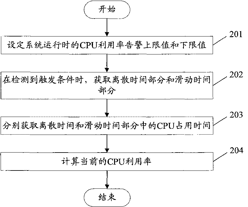
[0039] The embodiment of the present invention provides a method for detecting CPU utilization. By determining the accurate CPU utilization, it overcomes the periodic fluctuation of the existing system CPU utilization, which is prone to deviation and cannot truly reflect the current operating conditions. The amount of data is huge, and the data provided to the system monitoring personnel is not timely and inaccurate.

[0040] Firstly, Embodiment 1 of the present invention is introduced.

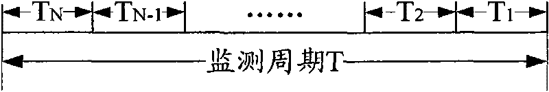
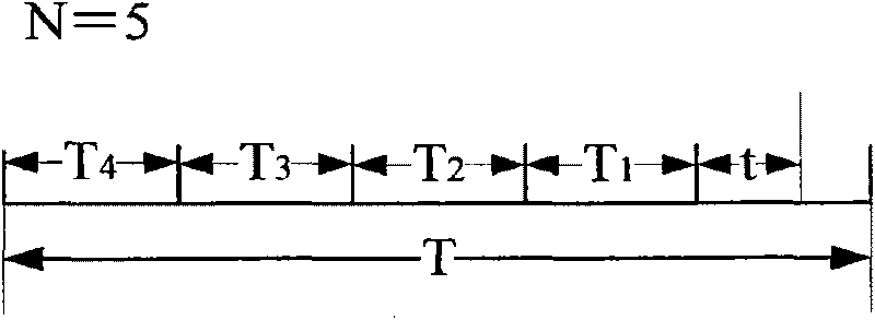
[0041] In the embodiment of the present invention, the trigger condition of CPU utilization detection is specifically an external command, and the time window structure used in the embodiment of the present invention is as follows figure 1 As shown, there is a discrete time point every other discrete interval on the time axis, from which N+1 continuous discrete time points (that is, N discrete intervals) are selected to form a time window, and when the current moment leaves the end of the tim...


PUM


Abstract

The invention provides a method and device for detecting CPU utilization ratio, which relates to an embedded system and solves the problem of inaccurate detection of the CPU utilization ratio. The method comprises the steps of: when a triggering condition is detected, determining a discrete time part and a sliding time part; respectively acquiring the CPU holding times of the discrete time part and the sliding time part; and computing to acquire the current CPU utilization ratio according to the CPU holding times of discrete time part and the sliding time part. The technical scheme provided by the invention is suitable for embedded systems.

Description

technical field [0001] The invention relates to an embedded system, in particular to a CPU utilization rate detection method and device. Background technique [0002] At present, there are more and more tasks running in the embedded system, the amount of data processed by the system is also increasing, and the requirements for system performance are getting higher and higher, so it is very important to monitor the operating status of the system in real time. The change of CPU utilization can reflect the current running status of the system and the running status of each task, which is an important criterion for system monitoring. The CPU utilization rate can explain the working status of the CPU. The higher the utilization rate, the higher the CPU is in the high-speed operation (busy) state. At this time, the heat is high. If the utilization rate exceeds 90%, it will easily crash after a long time. If the heat dissipation is not good, It can also cause the CPU to burn out, ...

Claims


Application Information

Patent Timeline
IPC IPC(8): G06F11/30
Inventor 祁云
Owner RAISECOM TECH
Why Eureka
Try Eureka