Improved racket threader

A stringing machine and improved technology, applied in the field of improved racket stringing machines, can solve the problems of inaccurate stringing, laboriousness, and inaccurate pounds.

Inactive Publication Date: 2010-06-16
林伯修 +1
View PDF0 Cites 6 Cited by
  • Summary
  • Abstract
  • Description
  • Claims
  • Application Information

AI Technical Summary

Problems solved by technology

[0005] 1. The above-mentioned racket stringing machine has its base rod and wire drawing head fixed at the same position and cannot be displaced, while the racket frame is threaded one by one in sequence, so there will be a clip between the racket frame and the outer string when viewed from above. Angle θ is generated, even after the racket frame turns, the clip still exists, so when the racket string is under tension, the racket frame is subjected to uneven force due to friction, resulting in inaccurate pounds; and there will be gaps between the racket frame perforation and the racket string Friction, damage, or even breakage, even if the threading is not broken, it may still cause the racket frame to break when it is used, reducing the service life of the racket frame and the string, and because of inaccurate threading, it will affect the performance of the game and even affect the performance of the racket. interest in the movement
[0006] 2. The racket threading machine is implemented by the operator on site. Due to the on-site operation, it is inevitable that the operator needs to suspend the operation and leave midway due to urgent matters. However, the racket stringing machine must be threaded after the entire racket frame is threaded from the beginning. Stop, otherwise the racket stringing machine will be powered off and stopped directly, which will make the racket strings on the racket frame loose and unable to maintain a tight state during the stringing process. In this way, after the operator restarts the power of the racket stringing machine again, all the racket strings After the threading is completed, the entire racket line will become loose and unusable, and it must be done again, which is not only troublesome but also time-consuming and laborious

Method used


Image

  • Improved racket threader
  • Improved racket threader
  • Improved racket threader

Examples


Embodiment Construction

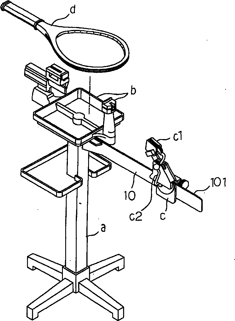
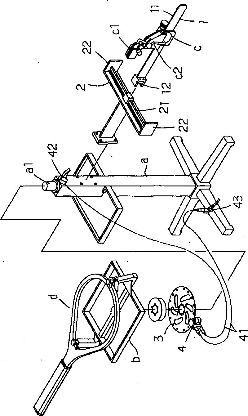
[0040] Please refer to image 3 As shown, in the improved racket stringing machine of the present invention, its improved structure includes a horizontal position adjusting device and a braking device of the stringing machine. The horizontal position adjustment device includes a base rod 1, a consolidation seat 2, and the racket threading machine mainly has a base a, a holding frame b and a wire drawing head c (this is the same as the above-mentioned conventional one, and will not be repeated here. ), the wiring head c has a puller c1 and a puller rod c2; where:

[0041] The base bar 1 is horizontal and used to combine with the wire-drawing head c. The base bar 1 is combined with a rack 11, so that the wire-drawing head c can be displaced according to the rack 11; and one end of the base bar 1 is fixed with a sliding seat 12. The sliding seat 12 is horizontal and fixed to the end of the base rod 1, and the cross section of the sliding seat 12 can be a U-shaped structure;

[...


PUM


Abstract

The invention discloses an improved racket threader. The improved part of the racket threader comprises a horizontal position regulation apparatus and a brake apparatus of the threader, wherein, the horizontal position regulation apparatus is fixedly connected with a base of the racket threader by utilizing a horizontal consolidated seat which is provided with a horizontal sliding rail and a basal rod capable of displacing, one end of the basal rod is pivoted on the sliding rail, a threader head arranged on the basal rod regulates the left and right horizontal positions along with the displacement of the basal rod, thus being capable of managing the threading work when the horizontal angle of a racket frame changes, the racket frame and the threader of the threader head are regulated to thread into a line, thus not wearing or damaging a basket to lead to accurate threading tension and enhancing quality and service life of threads. The brake apparatus and a clamping device are grouped on a rotary shaft in the base below a holding frame by utilizing a disk brake, and are respectively connected with two leads to a hand control switch and a foot control switch; when operators want to suspend in midway or leave, the effect of controlling the threader to suspend rotation can be conveniently achieved by a hand operation manner or a foot operation manner.

Description

technical field [0001] The present invention relates to an improved racket stringing machine, in particular to a racket stringing machine which combines the left and right horizontal position structure of the wire drawing head which can improve the stringing quality, and the braking device which provides the user with a pause or leave in the middle . Background technique [0002] Press, known racket stringing machine (as figure 1 As shown), it mainly has a base a, a holding frame b, and a cable head c; Positioning function, the wire pulling head c has a wire puller c1 and a wire rod c2, and the wire pulling head c is connected to the base a by a horizontal base rod 10, the base rod 10 is fixed on the top of the base a, To combine with the wire drawing head c, the base rod 10 is combined with a rack 101 so that the wire drawing head c can be displaced according to the rack 101 , that is, the wire drawing head c can be displaced relative to the base rod 10 . [0003] When i...

Claims


Application Information

Patent Timeline
Patent Type & Authority Applications(China)
IPC IPC(8): A63B51/14A63B51/16
Inventor 林伯修李俊杰
Owner 林伯修
Why Eureka
Try Eureka