Motor stator

A motor stator and stator technology, applied in the manufacture of stator/rotor body, magnetic circuit shape/style/structure, magnetic circuit static parts, etc., can solve problems such as bad phenomena and easy slack, and achieve high safety and durability Effect

Inactive Publication Date: 2018-04-06
XUZHOU NANPU ELECTRICAL TECH
View PDF5 Cites 2 Cited by
  • Summary
  • Abstract
  • Description
  • Claims
  • Application Information

AI Technical Summary

Problems solved by technology

[0003] The present invention is a new type of motor stator which is aimed at the cooperation between the 120 stator and the aluminum barrel in the current market, which is prone to looseness and bad phenomena in the case of long-term work.

Method used


Image

  • Motor stator
  • Motor stator

Examples


Embodiment Construction

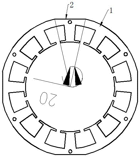
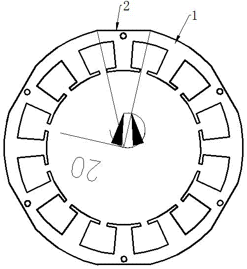
[0013] as attached figure 1 As shown, a motor stator includes a stator body 1, the cross-sectional profile of the stator body 1 is a circular structure, and 4 to 6 cut surfaces 2 are uniformly distributed around the outer edge of the stator body 1.

[0014] The length of the cut surface 2 is equal to the length of the stator body 1 .

[0015] The width of each cut plane 2 is equal, and the included angle of the arc corresponding to each cut plane 2 is not more than 30 degrees.

[0016] The included angle of the arc corresponding to each cut plane 2 is 20 degrees.

[0017] The number of the cut surfaces 2 is four.

[0018] The specific method of the present invention is: cut off a part of the outer contour of the stator on the basis of the original stator to form 4 to 6 effective planes, and add 4 planes to cooperate when the stator and the aluminum barrel are tightly matched. There will be no looseness in the case, making it safer and more durable.


PUM

PropertyMeasurementUnit
Angleaaaaaaaaaa
Angleaaaaaaaaaa

Abstract

The invention relates to a motor stator which comprises a stator body. A cross-sectional contour of the stator body is a circular structure, and four to six sections are uniformly distributed at the circumferential direction of an outer edge of the circular structure. Compared with an ordinary stator, the motor stator has no relaxation phenomenon under a long-term condition, the safety and durability performance are better, and a part of materials is saved so as to reduce cost and improve efficiency.

Description

technical field [0001] The invention relates to the field of motors, in particular to a motor stator. Background technique [0002] At present, the 120 stator commonly used in the market has a full circle shape, and when it is tightly matched with the aluminum barrel, it is a surface-to-surface fit, and it will appear slack and other bad performances under long-term conditions. Contents of the invention [0003] The present invention is a new type of motor stator aimed at the cooperation between the 120 stator and the aluminum barrel in the current market, which is prone to looseness and bad phenomena under the condition of long-time work. [0004] The present invention is achieved through the following technical solutions: a motor stator, including a stator body, the cross-sectional profile of the stator body is a circular structure, and 4 to 6 cut surfaces are evenly distributed around the outer edge of the stator body. [0005] The length of the cut surface is equal to...

Claims


Application Information

Patent Timeline
IPC IPC(8): H02K1/12H02K15/02
Inventor 谢秀斌
Owner XUZHOU NANPU ELECTRICAL TECH
Why Eureka
Try Eureka