Clamping compensation device for use in machining of plurality of workpieces

A compensation device and multi-workpiece technology, applied in the direction of clamping device, positioning device, metal processing equipment, etc., can solve the problems of insufficient processing accuracy, inability to realize equipment automation, low work efficiency, etc., and achieve the effect of ensuring processing accuracy

Inactive Publication Date: 2014-12-24
无锡振华机械有限公司
View PDF11 Cites 1 Cited by
  • Summary
  • Abstract
  • Description
  • Claims
  • Application Information

AI Technical Summary

Problems solved by technology

In order to solve the problem of insufficient machining accuracy caused by insufficient clamping of the workpiece, it is necessary to manually adjust the position of the workpiece compression sleeve on the slide seat, so that the distance between some workpiece compression sleeves and the workpiece positioning sleeve is reduced, and the workpiece is clamped. tight, but this method cannot realize the automation of the equipment, and the work efficiency is low

Method used


Image

  • Clamping compensation device for use in machining of plurality of workpieces
  • Clamping compensation device for use in machining of plurality of workpieces
  • Clamping compensation device for use in machining of plurality of workpieces

Examples


Embodiment Construction

[0015] The present invention will be described in further detail below in conjunction with the accompanying drawings.

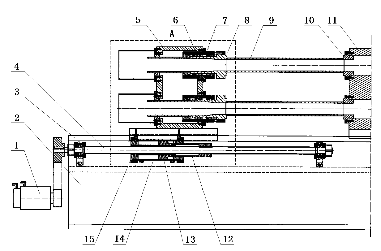
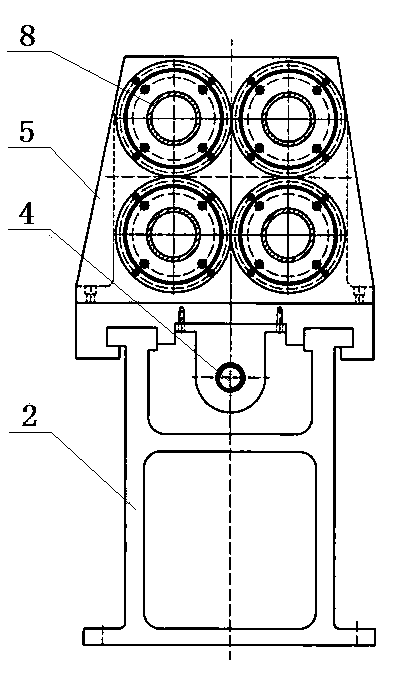
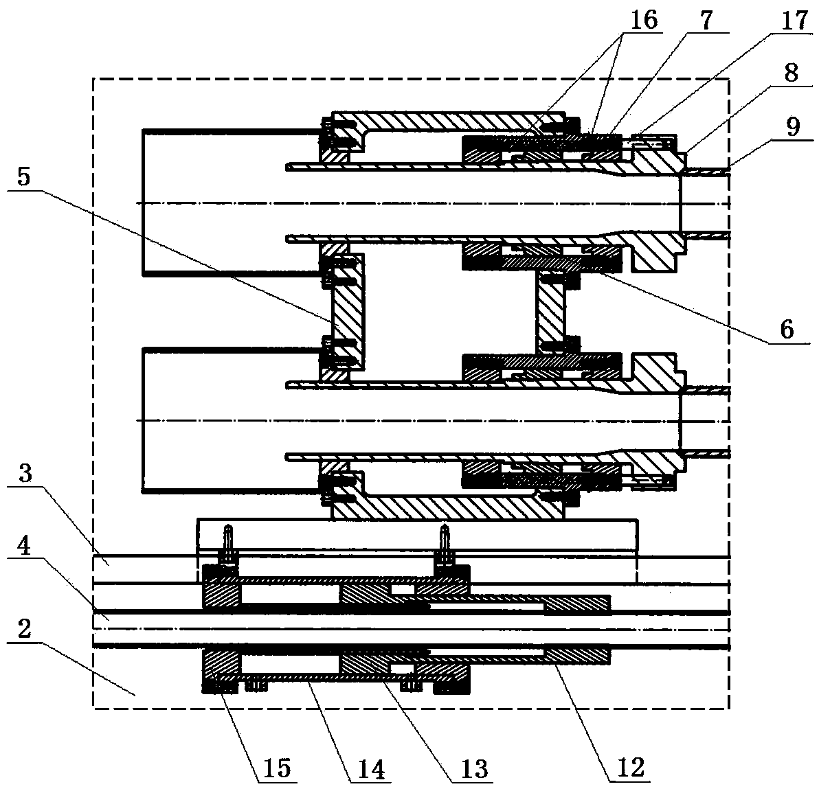
[0016] Such as Figure 1 to Figure 3 As shown, the clamping and compensating device for multi-workpiece processing of the present invention includes a frame 2 on which a sliding seat 5 and a fixing seat 11 are sequentially arranged longitudinally. The frame 2 corresponding to the slide seat 5 has a linear slide rail 3 arranged longitudinally, and there is a power mechanism between the slide seat 5 and the frame 2 that can push the slide seat 5 to slide along the linear slide rail 3 . Workpiece compression sleeve 8 is arranged. There is a through hole on the fixed seat 11 , and the end of the through hole adjacent to the sliding seat 5 has a workpiece positioning sleeve 10 . The number of the through holes and the workpiece compression sleeves 8 are the same and no less than two, and the positions of the workpiece positioning sleeves 10 on the through holes ...


PUM


Abstract

The invention relates to a clamping compensation device for use in machining of a plurality of workpieces. The clamping compensation device comprises a frame, wherein a sliding seat and a fixing seat are arranged in sequence along the longitudinal direction on the frame; workpiece compression sleeves are arranged on the sliding seat; the fixing seat is provided with through holes; one end, which is adjacent to the sliding seat, of each through hole is provided with a workpiece positioning sleeve; the quantities of the through holes and the workpiece compression sleeves are the same, and are not less than two; the positions of the workpiece positioning sleeves on the through holes and the workpiece compression sleeves correspond one by one. The clamping compensation device is characterized in that compensating devices are arranged between the workpiece compression sleeves and the sliding seat; the compensating devices comprise first cylinder bodies which are arranged on the workpiece compression sleeves in a sleeving manner; piston sleeves are fixed on segments of the workpiece compression sleeves positioned in the first cylinder bodies; the peripheries of the piston sleeves are in hermetic movable fit with the inner walls of the first cylinder bodies. Corresponding first cylinder body side walls at the two ends of the piston sleeves are provided with oil holes. When the device is used for clamping the plurality of workpieces, each workpiece can be clamped completely, so that the subsequent machining accuracy of the workpieces can be ensured; meanwhile, automation of equipment can be realized, and the working efficiency is increased.

Description

technical field [0001] The invention relates to a fixture, in particular to a clamping compensation device used when multiple workpieces need to be processed simultaneously. Background technique [0002] As we all know, in the field of mechanical processing, in order to improve work efficiency, it is necessary to process multiple workpieces at the same time in many occasions. At this time, it is necessary to use a clamping device to clamp these workpieces at the same time, otherwise the purpose of simultaneous processing cannot be achieved. [0003] The traditional clamping devices all include a frame (or platform), on which a sliding seat and a fixed seat are arranged in sequence along the longitudinal direction; the frame corresponding to the sliding seat has linear slide rails arranged in the longitudinal direction, and the sliding seat and the machine There is a power mechanism between the frames that can push the sliding seat to slide along the linear slide rail, and th...

Claims


Application Information

Patent Timeline
Patent Type & Authority Applications(China)
IPC IPC(8): B23Q3/06B23Q3/08
CPCB23Q3/061B23Q3/08B23Q23/00B23Q2703/04B23Q2703/08
Inventor 杨国社宋为标
Owner 无锡振华机械有限公司
Why Eureka
Try Eureka