Upper die buffering mechanism of miniature stamping equipment

A technology of stamping equipment and buffer mechanism, which is applied in the field of upper die buffer mechanism, can solve problems such as increased cost, poor coaxiality and motion stability, and affects sliding fit accuracy, and achieves the effects of avoiding breakage, high stability, and reliable positioning

Inactive Publication Date: 2010-06-16
苏州托克斯冲压设备有限公司
View PDF1 Cites 2 Cited by
  • Summary
  • Abstract
  • Description
  • Claims
  • Application Information

AI Technical Summary

Problems solved by technology

This structure is simple, practical and stable, but its biggest shortcoming is that when the upper mold touches any object or encounters any resistance during the downward process, a force stroke will occur.
[0006] 1. The process of slotting on the upper piston rod (103) and the lower piston rod (104) and installing the positioning pin (141) is more complicated, which increases the cost and easily affects the upper piston rod (103) and the lower piston rod (103). 104) Sliding fit accuracy between
[0007] 2. The positioning pin (141) slides in the guide groove (142), and there is a risk of fracture due to the influence of gravity and inertia
[0008] 3. The piston upper rod (103) and the piston lower rod (104) are nested and connected with the outer shaft (120) through the step shaft (130), and there is a certain gap between the shaft and the sleeve, resulting in coaxiality and stable movement Poor sex

Method used


Image

  • Upper die buffering mechanism of miniature stamping equipment
  • Upper die buffering mechanism of miniature stamping equipment
  • Upper die buffering mechanism of miniature stamping equipment

Examples


Embodiment 1

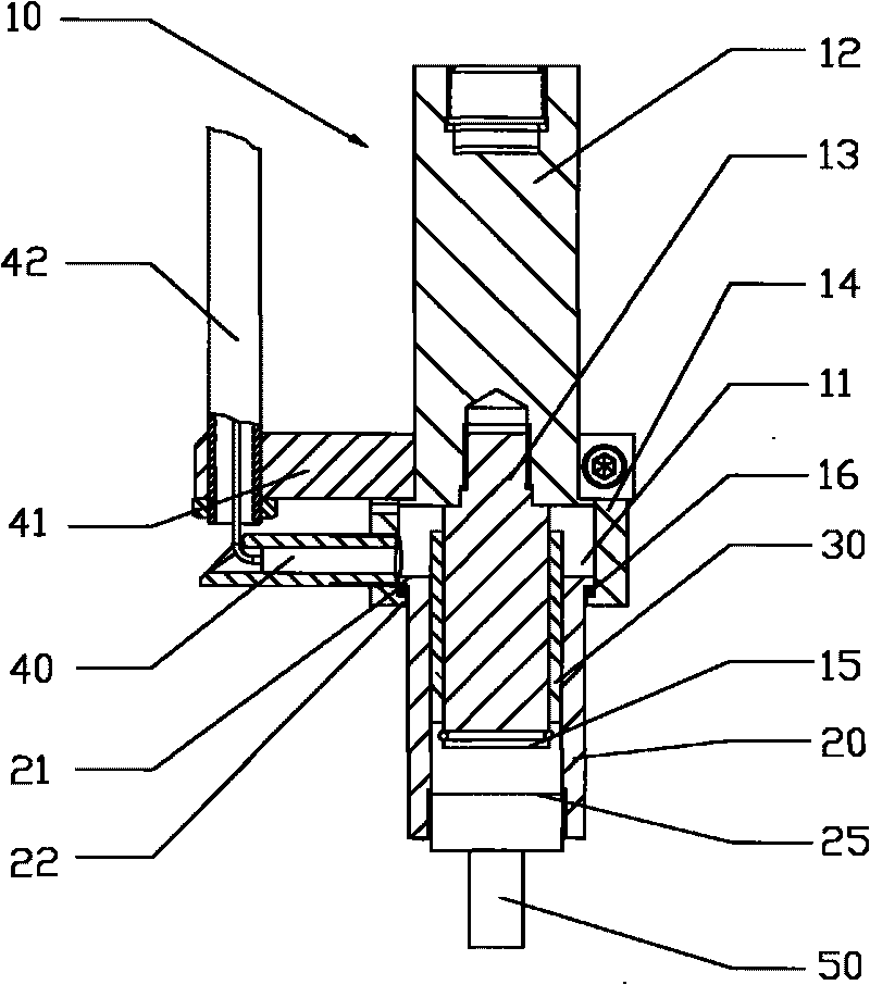
[0026] As attached figure 2 As shown, the upper mold buffer mechanism in this embodiment includes:

[0027] The working piston 10 is composed of a piston rod 12 and a connecting shaft 13 fixedly connected to each other. The piston rod 12 and the connecting shaft 13 are connected by threads. The working piston also has an annular wall 14 which is connected to the piston rod 12 Coaxial, and the upper end is fixedly connected with the piston rod 12;

[0028] A sliding sleeve 20 sleeved outside the connecting shaft 13 is sandwiched between the annular wall 14 and the piston rod 12, and the upper mold 50 is fixedly installed at the lower end of the sliding sleeve 20.

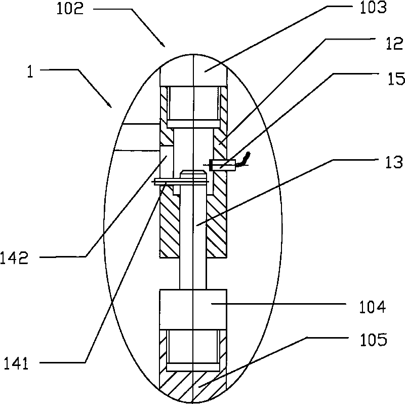
[0029] At the upper end of the sliding sleeve 20, a ring-shaped boss 21 is protruding outward in the radial direction; at the lower end of the ring-shaped wall 14 there is a ring-shaped limiting block 22 protruding inward. The space above the block 22 forms an annular positioning groove 11 coaxial with the working piston ...

Embodiment 2

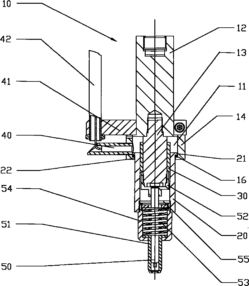
[0036] As attached image 3 As shown, the difference between Embodiment 2 and Embodiment 1 is that the upper mold 50 is fixed to the bottom of the connecting shaft 13 by the upper mold fixing sleeve 52. On the outer side of the upper mold 50, a mechanism for assisting demolding is provided. The mechanism includes a spring fixing sleeve 54 corresponding to the downward extension of the sliding sleeve 20, and a demolding spring 53 is clamped in the spring fixing sleeve 54 , The upper mold 50 passes through the center of the ejection spring 53. On the top of the ejection spring 53, a spring base 55 is fixedly provided. A demolding sleeve 51 is nested at the lower end of the spring fixing sleeve 54. The demolding sleeve 51 can slide longitudinally relative to the demolding fixing sleeve 54 so as to push the demolding spring 53 upward.

[0037] When the working piston 10 drives the sliding sleeve 20 to move downwards, once the lower surface of the stripping sleeve 51 touches an obje...


PUM


Abstract

The invention discloses an upper die buffering mechanism of miniature stamping equipment, which comprises a working piston and a slide element, wherein the slide element can be slidably arranged along the axial direction of the working piston. The upper die buffering mechanism of the miniature stamping equipment is characterized in that the slide element and the working piston are coaxially sleeved at a slide sleeve outside the working piston; and in the whole slide stroke, the lower surface of the slide sleeve is not higher than that of the working piston; the lower end of the working piston is provided with an annular positioning groove; the positioning groove extends along the axial direction of the working piston; the upper end of the slide sleeve is convexly provided with an annular boss which is coaxial with the slide sleeve along the radial direction, and the boss can just slide in the positioning groove. The structure has stable slide, precise matching, convenient installation and low application cost.

Description

Technical field [0001] The present invention relates to a safety device for stamping equipment, and more specifically, to design an upper die buffer mechanism of a small stamping equipment. Background technique [0002] The upper die in the existing small stamping equipment is fixed on the working piston of the cylinder by a fixed die device. Under the action of the working pressure, the force can be directly transmitted to the head of the upper die to meet the requirements of the stamping workpiece. This structure is simple, practical and stable, but its biggest shortcoming is that when the upper mold is in the downward process, once it touches any object or encounters any resistance, it will generate a force stroke. Therefore, in the event of an operation mistake touching a human hand or other objects, it will cause a personal accident or an equipment accident. [0003] In order to solve the above problems, the applicant applied for an invention patent (200810019940.X, safety de...

Claims


Application Information

Patent Timeline
IPC IPC(8): B21D37/10B21D45/02
Inventor 许峰
Owner 苏州托克斯冲压设备有限公司
Why Eureka
Try Eureka