Circumferential tooth gap measuring and coloring positioning device for bevel gear pair

A technology of bevel gear pair and positioning device, which is applied in the testing of measuring devices, transmission parts, mechanical parts, etc., can solve the problems of difficult operation, small space, low measurement repeatability, etc., and achieve the effect of stable and reliable positioning.

Pending Publication Date: 2019-03-29
ZHONGNAN TRANSMISSION MACHINERY FACTORY CHANGSHAAVIATION IND
View PDF0 Cites 2 Cited by
  • Summary
  • Abstract
  • Description
  • Claims
  • Application Information

AI Technical Summary

Problems solved by technology

The defects and deficiencies of this method are mainly reflected in: 1. During assembly, the operation can only be performed from the observation window of the oil surface of the shell, and the space is small, so the operation is difficult; 2. The sticking positi

Method used


Image

  • Circumferential tooth gap measuring and coloring positioning device for bevel gear pair
  • Circumferential tooth gap measuring and coloring positioning device for bevel gear pair
  • Circumferential tooth gap measuring and coloring positioning device for bevel gear pair

Examples


Embodiment Construction

[0022] The present invention will be further described in detail below in conjunction with the accompanying drawings and specific embodiments.

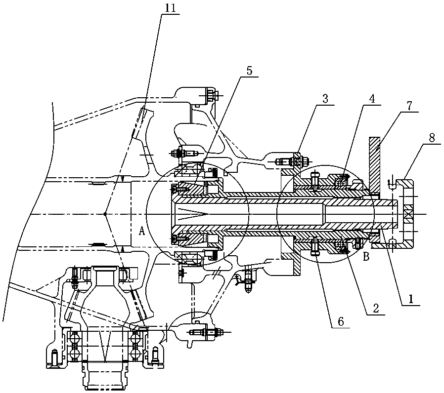
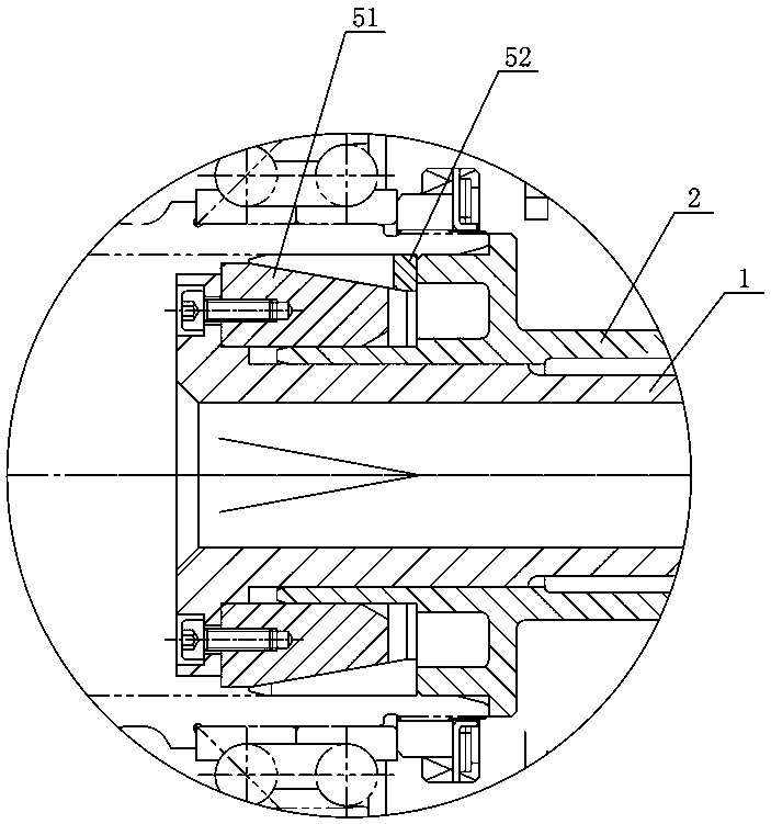
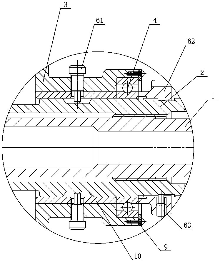
[0023] Figure 1 to Figure 3 It shows an embodiment of the present invention's circumferential backlash measurement and coloring positioning device for bevel gear pairs, including tension shaft 1, compression shaft 2, fixed frame 3, bearing 4, expansion group 5 and locking Group 6, the fixed frame 3 is fixed on the housing of the reducer at the output end, the bearing 4 is installed on the fixed frame 3, the pressing shaft 2 is socketed with the bearing 4 and extends into the output gear 11, and the tensioning shaft 1 is installed on the The compression shaft 2 is connected with the compression shaft 2 by threads, the end of the tension shaft 1 close to the output gear 11 exceeds the compression shaft 2, and the expansion group 5 is installed on the excess end of the tension shaft 1 and connected to the inner wall of the output gear 1...


PUM


Abstract

The invention discloses a circumferential tooth gap measuring and coloring positioning device for a bevel gear pair. The device comprises a tension shaft, a pressing shaft, a fixing frame, a bearing,an expansion group, and a locking group. The fixing frame is fixedly installed on a shell of an output end speed reducer. The bearing is installed on the fixing frame. The pressing shaft is sleeved with the bearing and extends into an output gear. The tension shaft penetrates through the pressing shaft, is in threaded connection with the pressing shaft, and exceeds the pressing shaft by an end part of the output gear. The expansion group is installed at an over end of the tension shaft and is in expansion with the inner wall of the output gear. The locking group is installed on the fixing frame and the pressing shaft, and locks and positions the axial and radial directions of the pressing shaft. The device has the advantages of being simple and convenient to operate, free of pollution, andcapable of realizing rotation stop positioning and coloring inspection.

Description

technical field [0001] The invention mainly relates to the technology for measuring the circumferential backlash after the bevel gear pair of the reducer is assembled, in particular to a measuring and coloring positioning device for the circumferential backlash of the bevel gear pair. Background technique [0002] According to the requirements of "Instructions for Tail Reduction Assembly in Transmission System", it is necessary to measure the actual circumferential backlash of the bevel gear pair in the transmission system after assembly. [0003] The method used in the field is to stick lead wire on the tooth surface of the bevel gear, and after rotating the gear to flatten the lead wire, measure the thickness of the flattened lead wire to obtain the backlash value. The defects and deficiencies of this method are mainly reflected in: 1. During assembly, the operation can only be performed from the observation window of the oil surface of the shell, and the space is small, s...

Claims


Application Information

Patent Timeline
IPC IPC(8): G01B21/16G01M13/021F16H57/023
CPCG01B21/16F16H57/023G01M13/021
Inventor 莫晓辉彭伟叶绿柯
Owner ZHONGNAN TRANSMISSION MACHINERY FACTORY CHANGSHAAVIATION IND
Why Eureka
Try Eureka