

Artificial lens forming mold
A technology for molding molds and intraocular lenses, which is applied in the fields of intraocular lenses, prostheses, and medical sciences. It can solve problems that affect the molding effect and mold molding impact, so as to eliminate internal pressure, ensure reliable positioning, and ensure stability and reliability. Effect
- Summary
- Abstract
- Description
- Claims
- Application Information
AI Technical Summary
Problems solved by technology
Method used
Image

Examples
Embodiment 1
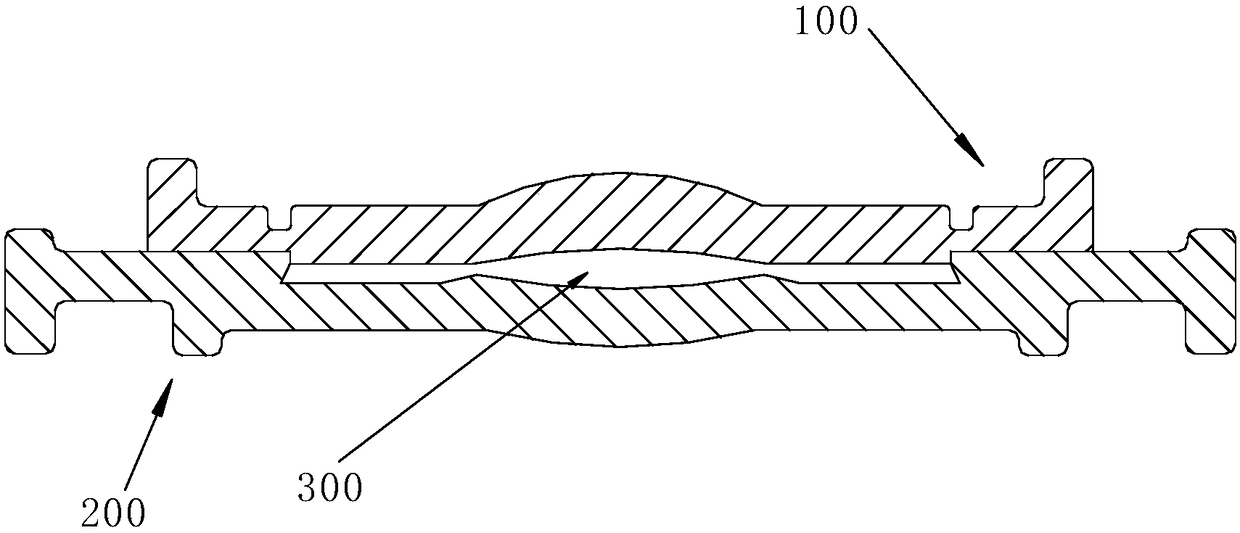
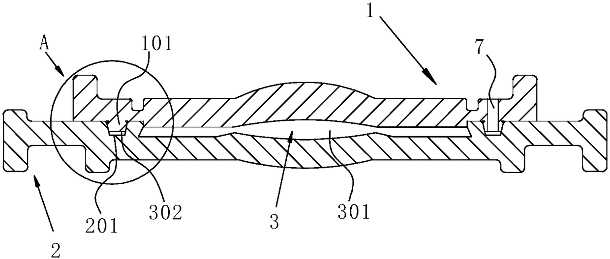
[0085] Such as image 3 As shown, a mold for forming an intraocular lens includes a male mold 1 and a female mold 2, the male mold 1 is arranged above the female mold 2, and the middle area of the male mold 1 is an upwardly convex arc-shaped area, and the arc-shaped area of the The centerline is the centerline of the first optical zone of the male mold 1; The bottom of the male mold 1 is rotated and extended around the circumferential direction with a positioning boss 101, and the positioning boss 101 is located outside the first optical zone, as Figure 5 As shown, the positioning boss 101 is an annular boss, the cross-sectional shape of the positioning boss 101 is trapezoidal, and the rotation axis of the positioning boss 101 is on the same straight line as the centerline of the first optical zone. The top of the female mold 2 is rotated and extended around the circumferential direction to be provided with a positioning groove 201, and the positioning groove 201 is loca...
Embodiment 2
[0094] The difference between this embodiment and Embodiment 1 is:
[0095] The cross-sectional shape of the conduction opening is circular. In other embodiments, the cross-sectional shape of the conduction opening may also be a parallelogram.
Embodiment 3
[0097] The difference between this embodiment and Embodiment 1 is:
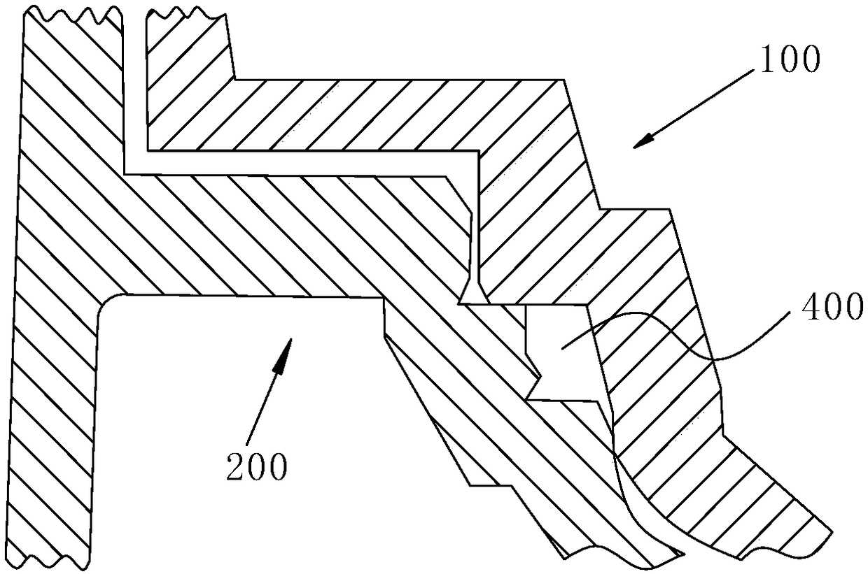
[0098] In this embodiment, if Figure 8 As shown, the cross-sectional shape of the positioning boss 101 and the positioning groove 201 is a rectangle, wherein the protruding end of the positioning boss 101 is provided with a boss chamfer 6, the cross-sectional shape of the positioning boss 101 is designed as a rectangle, and in the positioning The protruding end of the boss 101 is provided with a boss chamfer 6, which can ensure that the positioning boss 101 can be easily inserted into the positioning groove 201, and at the same time can reduce the difficulty of making the mold and simplify the manufacturing process, thereby reducing the manufacturing cost.
[0099] Of course, in other embodiments, the cross-sectional shape of the positioning boss and the positioning groove can also be triangular. Setting a triangular shape can not only facilitate quick positioning, but also save material. The cross-sectiona...
PUM
 Abstract
Description
Claims
Application Information