Synchronous transmission mechanism for yarn feeder

A technology of synchronous transmission and yarn feeder, applied in textiles and papermaking, weft knitting, knitting, etc., can solve the problems of inconvenient use, complex structure of gear pulleys, and inability to adjust the length of toothed belts, etc. Simple, easy-to-market effects

Inactive Publication Date: 2010-06-16
吴江天龙针织有限公司
View PDF0 Cites 4 Cited by
  • Summary
  • Abstract
  • Description
  • Claims
  • Application Information

AI Technical Summary

Problems solved by technology

With such a structure, not only the structure of the geared pulley is complicated, but also the length of the matched toothed belt cannot be adjusted, making it inconvenient to use
Therefore, the manufacturer must produce toothed belts of various specifications and lengths in advance for customers to choose and purchase, which brings great inconvenience to the manufacturer, seller, and user.

Method used


Image

  • Synchronous transmission mechanism for yarn feeder
  • Synchronous transmission mechanism for yarn feeder
  • Synchronous transmission mechanism for yarn feeder

Examples


Embodiment Construction

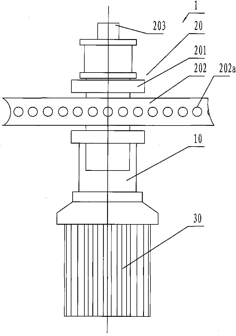
[0020] figure 2 It is a structural schematic diagram of a single yarn feeder in the present invention. Such as figure 2 As shown, a yarn feeder 1 mainly includes a frame 10 , a synchronous transmission mechanism 20 , and a yarn storage device 30 . The synchronous transmission mechanism 20 is mainly composed of transmission wheels 201 of a plurality of yarn feeders arranged in a circle and an endless synchronous belt 202 . The transmission wheel 201 is installed above the yarn storage device 30, and the transmission wheel 201 and the yarn storage device 30 are installed on the frame 10 respectively.

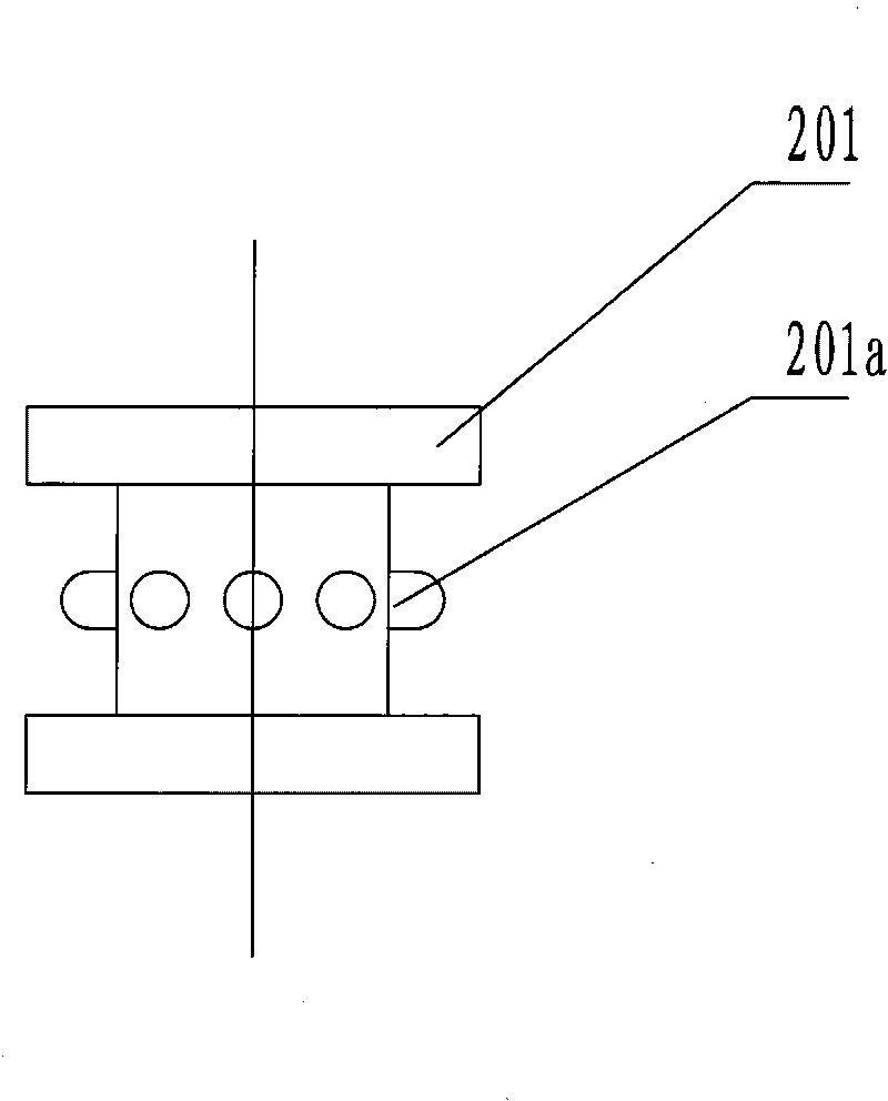
[0021] image 3 It is a structural schematic diagram of the transmission wheel 201, combined with figure 2 and image 3 Viewing, the transmission wheel 201 is provided with a shaft hole (not shown in the figure) in the center, and a transmission shaft 203 and a bearing (not shown in the figure) are arranged in the shaft hole. Through this structure, the transmission wheel...


PUM


Abstract

The invention relates to a synchronous transmission mechanism for a yarn feeder, which comprises transmission wheels of a plurality of yarn feeders arranged circumferentially, and an annular synchronous belt; outer edges of the transmission wheels are provided with a plurality of bulges circling at equal intervals; and the annular synchronous belt is provided with a plurality of concave holes in a mode that the concave holes are at the same interval lengths as the transmission wheels, so that the bulges are matched with the concave holes. The transmission mechanism is simple in structure and convenient to machine; and simultaneously, based on the characteristics of the transmission mechanism, users can cut the synchronous belt freely to the appropriate length according to requirements, so that the synchronous belt can be linked up for use, and the synchronous transmission mechanism brings great convenience to the users, manufacturers and retailers.

Description

technical field [0001] The invention relates to a synchronous transmission mechanism of a yarn feeder. Background technique [0002] In the circular weft machine, the yarn feeder is an important device for conveying the yarn on the knitting circular weft machine. It is the previous work for the circular weft machine to supply the knitting needles and use the yarn for knitting. Through this work, the yarn tension and The tension fluctuates, thereby steadily providing the yarn with the proper tension to make the cloth surface smooth. [0003] Currently commonly used yarn feeders, such as figure 1 As shown, the yarn feeder is mainly composed of a frame A, a pulley B, a yarn storage wheel C, and a parking mechanism D. Wherein, the belt pulley B and the yarn storage device C are respectively arranged on the upper and lower ends of the frame A, and are connected by a transmission shaft E. Pulley B puts the supplied belt F on it, so as to connect and drive the yarn storage wheel...

Claims


Application Information

Patent Timeline
Patent Type & Authority Applications(China)
IPC IPC(8): D04B15/58D04B15/48
Inventor 朱娟
Owner 吴江天龙针织有限公司
Why Eureka
Try Eureka