
Barrel cover shaped slot end surface mechanical sealing structure capable of rotating bilaterally

A technology of end face mechanical seal and two-way rotation, which is applied in the direction of engine sealing, mechanical equipment, engine components, etc., can solve the problems of weak fluid dynamic pressure characteristics, insufficient fluid film rigidity, and sealing surface wear, so as to facilitate design and production, Simple shape and structure, the effect of improving stability

Pending Publication Date: 2018-04-13
温州市天成密封件制造有限公司 +1
View PDF0 Cites 4 Cited by
  • Summary
  • Abstract
  • Description
  • Claims
  • Application Information

AI Technical Summary

Problems solved by technology

Although the two-way groove has no restriction on the rotation direction of the shaft, its hydrodynamic pressure characteristics are not strong, and the rigidity of the fluid film is insufficient.
Due to the lack of sufficient hydrodynamic pressure characteristics of most bidirectional groove types, the seal end face clearance is too small. At this time, system pressure fluctuations and rotor disturbances often cause end face collisions, which cause seal face wear and premature failure

Method used


Image

  • Barrel cover shaped slot end surface mechanical sealing structure capable of rotating bilaterally
  • Barrel cover shaped slot end surface mechanical sealing structure capable of rotating bilaterally
  • Barrel cover shaped slot end surface mechanical sealing structure capable of rotating bilaterally

Examples


Embodiment Construction

[0023] The following will clearly and completely describe the technical solutions in the embodiments of the present invention with reference to the accompanying drawings in the embodiments of the present invention. Obviously, the described embodiments are only some, not all, embodiments of the present invention. Based on the embodiments of the present invention, all other embodiments obtained by persons of ordinary skill in the art without making creative efforts belong to the protection scope of the present invention.

[0024] In order to make the above objects, features and advantages of the present invention more comprehensible, the invention will be further described in detail below in conjunction with the accompanying drawings and specific embodiments.

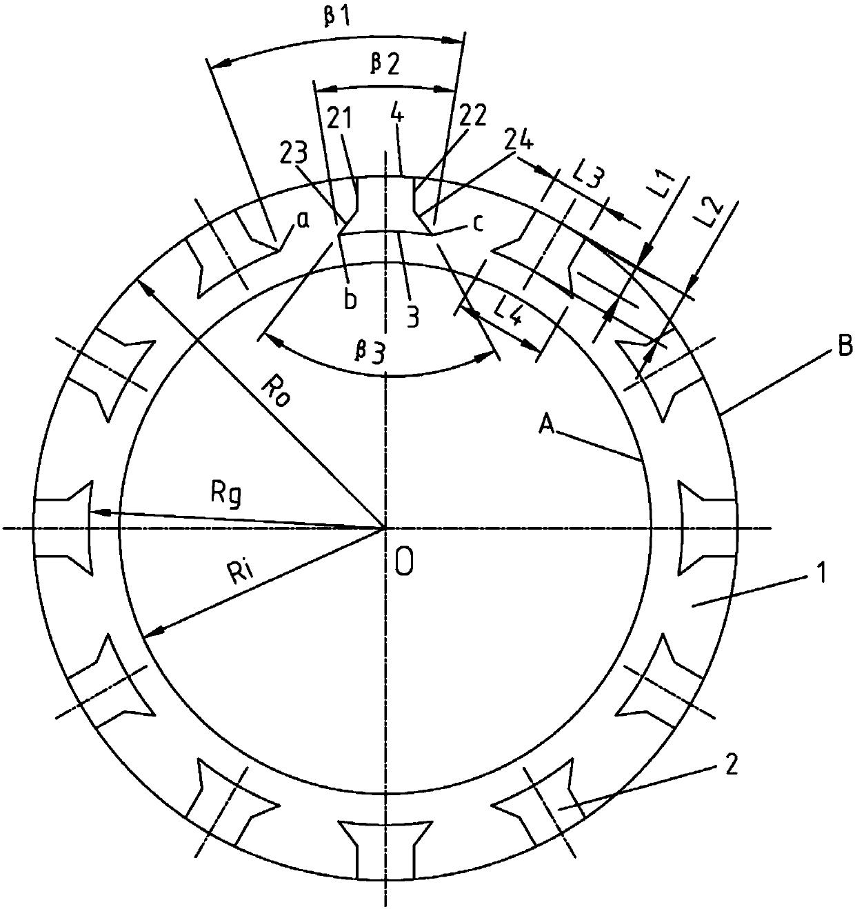
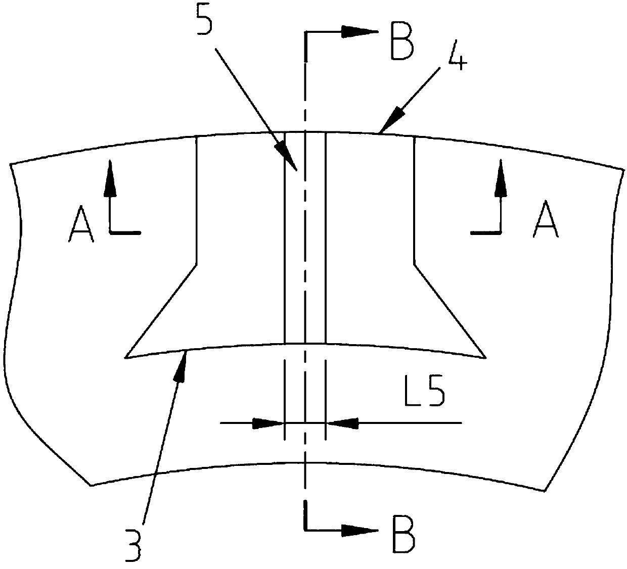
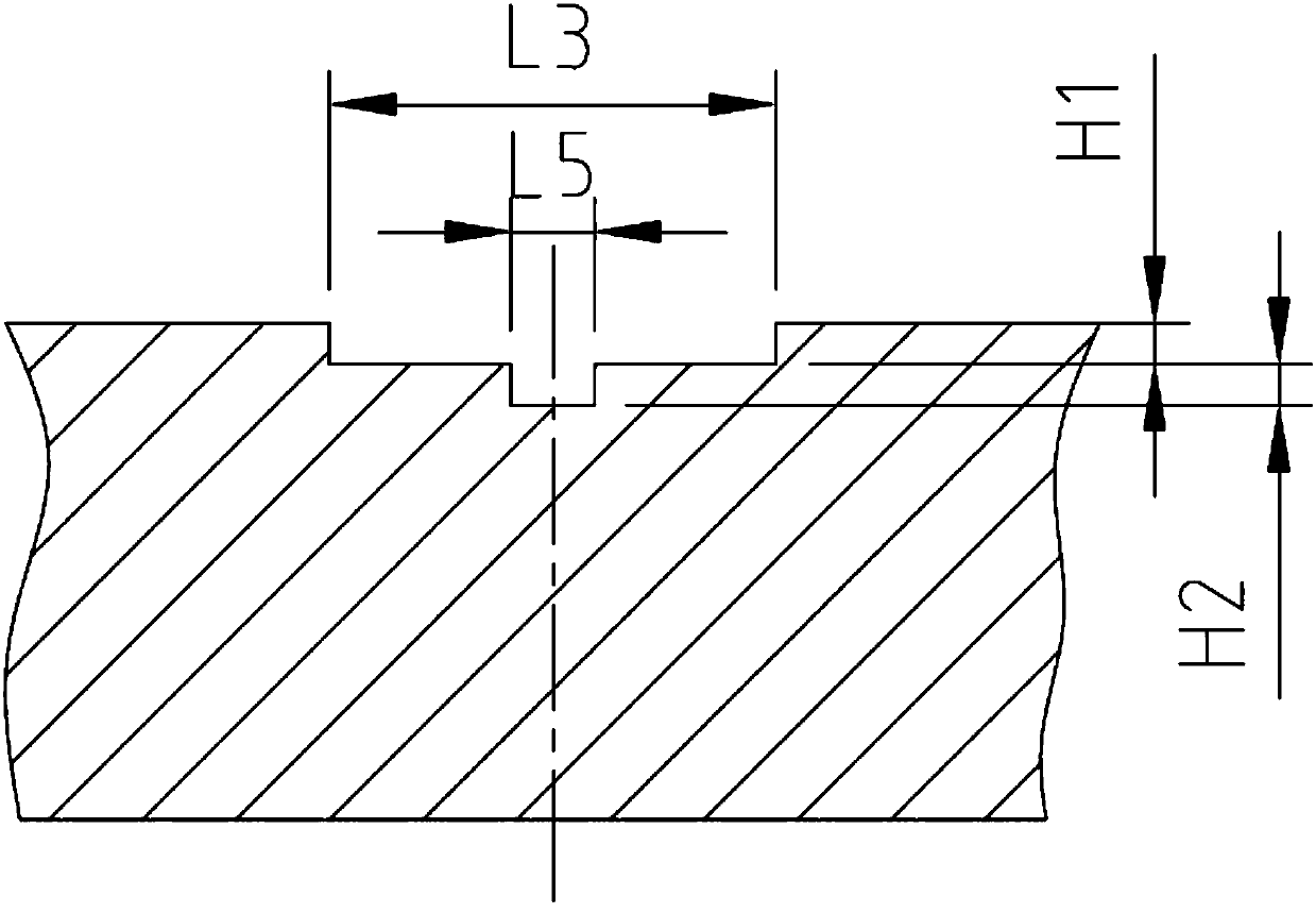
[0025] like Figure 1-5 As shown, the present invention provides a bidirectionally rotatable barrel-type groove end face mechanical seal structure, including a moving ring and a static ring of the mechanical seal, and at ...


PUM

PropertyMeasurementUnit
Groove depthaaaaaaaaaa
Widthaaaaaaaaaa

Abstract

The invention discloses a barrel cover shaped slot end surface mechanical sealing structure capable of rotating bilaterally. The barrel cover shaped slot end surface mechanical sealing structure comprises a rotating ring and a static ring, which are mechanically sealed, wherein a plurality of barrel cover shaped fluid dynamic pressure slots which are uniformly distributed in the peripheral direction are formed in at least one sealing end surface of the rotating ring or the static ring, and the dynamic pressure slots are symmetrical with respect to the radial center lines of the dynamic pressure slots; and each dynamic pressure slot comprises a slot hole, slot walls and a slot root which are sequentially connected, the slot hole is formed in the high-pressure side of the sealing end surface, the slot root is arranged at the low-pressure side of the sealing end surface, the slot walls comprise a rectangular slot wall and a tapered slot wall which are sequentially connected, the rectangular slot wall is connected with a small tapered surface of the tapered slot wall, and a large tapered surface of the tapered slot wall is connected with the slot root to form a sharp corner shaped convergence structure. The barrel cover shaped slot end surface mechanical sealing structure is simple in shape structure, and is convenient to design and produce. When the rotating rings of the device positively or negatively rotate along with a rotary shaft, continuous and stable fluid films can be formed between the sealing end surfaces of the rotating rings and the sealing end surfaces of the static rings.

Description

technical field [0001] The invention relates to a bidirectionally rotatable non-contact fluid dynamic pressure type mechanical seal end face structure, in particular to a bidirectionally rotatable cylinder cover type groove end face mechanical seal structure. Background technique [0002] Mechanical seals are divided into contact and non-contact. The non-contact mechanical seal does not touch each other during operation, the end faces are not worn, the power consumption is very small, and it can work normally even under high-speed and high-pressure conditions. Compared with ordinary contact mechanical seals, the biggest feature of non-contact mechanical seals is that there are shallow or deep grooves on the sealing end surface with a depth of several microns to several millimeters. When the shaft rotates, these grooves can generate fluid dynamic pressure, so that a small gap of a few microns is maintained between the sealing end faces, and there is a gas film or a liquid fi...

Claims


Application Information

Patent Timeline
IPC IPC(8): F16J15/34
CPCF16J15/34
Inventor 梁开洪
Owner 温州市天成密封件制造有限公司
Learn More