Measurement of wheel and/or axle load of road vehicles

A flexible, metal plate technology for applications in the field of dynamic weighing instruments

Active Publication Date: 2010-06-16
INTERNATIONAL ROAD DYNAMICS
View PDF5 Cites 9 Cited by
  • Summary
  • Abstract
  • Description
  • Claims
  • Application Information

AI Technical Summary

Problems solved by technology

With such a device it is only possible to determine the bending stresses loaded to the plate by the wheels

Method used


Image

  • Measurement of wheel and/or axle load of road vehicles
  • Measurement of wheel and/or axle load of road vehicles
  • Measurement of wheel and/or axle load of road vehicles

Examples


Embodiment Construction

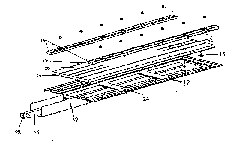
[0037] figure 1 description of

[0038] Such as figure 1As shown, the dynamic weighing instrument 10 of one embodiment of the present invention includes a substantially cuboid frame 12 including means, such as vertical mounting arms 14, to secure the frame 12 to a road surface (not shown). out). The flexible deformable sheet system 20 (so-called BENDING PLATE TM SYSTEM) is also basically in the shape of a cuboid. It will be described in more detail below. This view shows the upper flexibly deformable metal plate 16 , the lower or bottom metal plate 24 , the conductive wires or cables 58 and the longitudinally extending channel 52 .

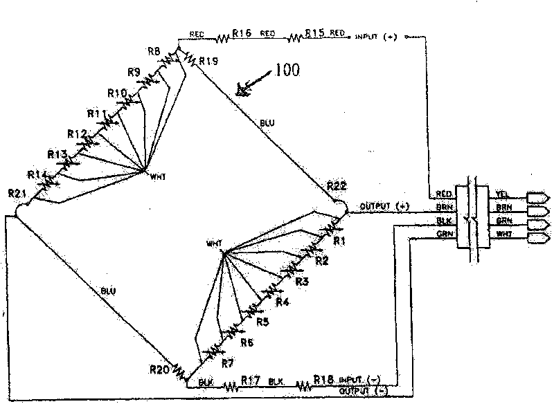
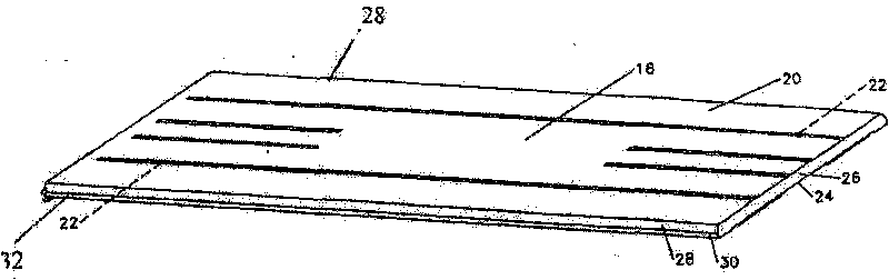
[0039] figure 2 , image 3 and Figure 4 description of

[0040] Such as figure 2 , image 3 and Figure 4 As shown, a flexibly deformable sheet system 20 of one embodiment of the present invention is embedded in substantially cuboid-shaped plates 16, 24 with a hollow and narrow space or volume 15 therebetween (eg, figure 1 b...


PUM


Abstract

The present invention provides an improved weigh-in-motion scale. A slight increase in the thickness of a an upper, flexibly-deformable metal plate in a thin, flexibly-deformable plate system coupled with a change in the transverse locations of the load cells provides the improved weigh-in-motion scale, which is capable of weighing substantially heavier loads than previously known weigh-in-motionscales. In use, as weight is applied to the weigh-in-motion scale, the upper flexibly-deformable metal plate elastically bends. The strain gauges thus provide a changing resistive value proportional to the bending of the flexible element and the weight applied, to generate signals to the Wheatstone bridge circuit, which then provides output signals from the Wheatstone bridge circuit, which are proportional to the force applied to the upper flexibly-deformable metal plate.

Description

technical field [0001] The present invention relates to a weigh-in-motion scale for wheel and / or axle load measurement of road vehicles. More particularly, the present invention relates to a weighing scale that utilizes a load sensing structure for generating an electrical signal indicative of a load on the weighing scale. Background technique [0002] Wheel and / or axle load measuring panels are known in the art and utilize one or more strain gauges connected to appropriate circuitry responsive to deformation of the measuring panel for signaling, indicating, Record or store wheel or axle loads. Furthermore, wheel loaders using strain gauge sensors fixed to deflectable load cells are known. However, the particular structure of the load cells used in prior art scales, the arrangement of the load cells within the housing structure of these scales, and the actuating or inactive elements of these prior art scale devices Collaboration between these, often results in complex and...

Claims


Application Information

Patent Timeline
Patent Type & Authority Applications(China)
IPC IPC(8): G01G3/14G01G19/03
CPCG01G19/022
Inventor 特伦斯·阿瑟·贝尔甘兰德尔·勒罗伊·汉森
Owner INTERNATIONAL ROAD DYNAMICS
Why Eureka
Try Eureka