
Real time monitoring system adopting GIS for underground installation of ubiquitous base plate

A real-time monitoring and basic technology, applied in general control systems, control/regulation systems, instruments, etc., can solve the objective evaluation plan that cannot be managed, meaningless, and lacks the completeness of new facilities and repairs, etc. problems, to achieve effective safety management and prevent danger

Inactive Publication Date: 2010-06-16
仁荷大学教产学协力团
View PDF0 Cites 0 Cited by
  • Summary
  • Abstract
  • Description
  • Claims
  • Application Information

AI Technical Summary

Problems solved by technology

[0005] However, underground sewers and sewers buried underground have the following problems. As long as people do not directly spend time to manage and inspect them, they cannot effectively manage a large number of facilities, and it is almost impossible to manage them in accordance with established reports. The actual situation is that, as a local government, the observation map related to the water supply and sewage within the management is not constituted by removing a part of the area.
[0006] In addition, even in the case of a GIS-based monitoring system, almost all of them only display the position of the measuring instrument on the map, and simply show the form of the measured value, so the GIS information and measurement information that invest a lot of money are due to A graph representing a nonsensical shift line without meaning
[0007] Therefore, even when a monitoring system is formed, there is no objective evaluation plan and business effect for the completeness of new installations and repairs of facilities buried underground between the main body that creates the facilities and the main body that manages them. prompt schemes that often produce contradictory material

Method used


Image

  • Real time monitoring system adopting GIS for underground installation of ubiquitous base plate
  • Real time monitoring system adopting GIS for underground installation of ubiquitous base plate
  • Real time monitoring system adopting GIS for underground installation of ubiquitous base plate

Examples


Embodiment Construction

[0043] The present invention will be specifically described below with reference to the accompanying drawings.

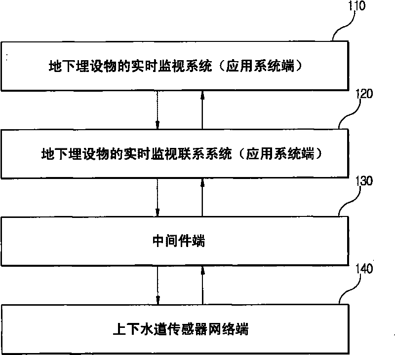
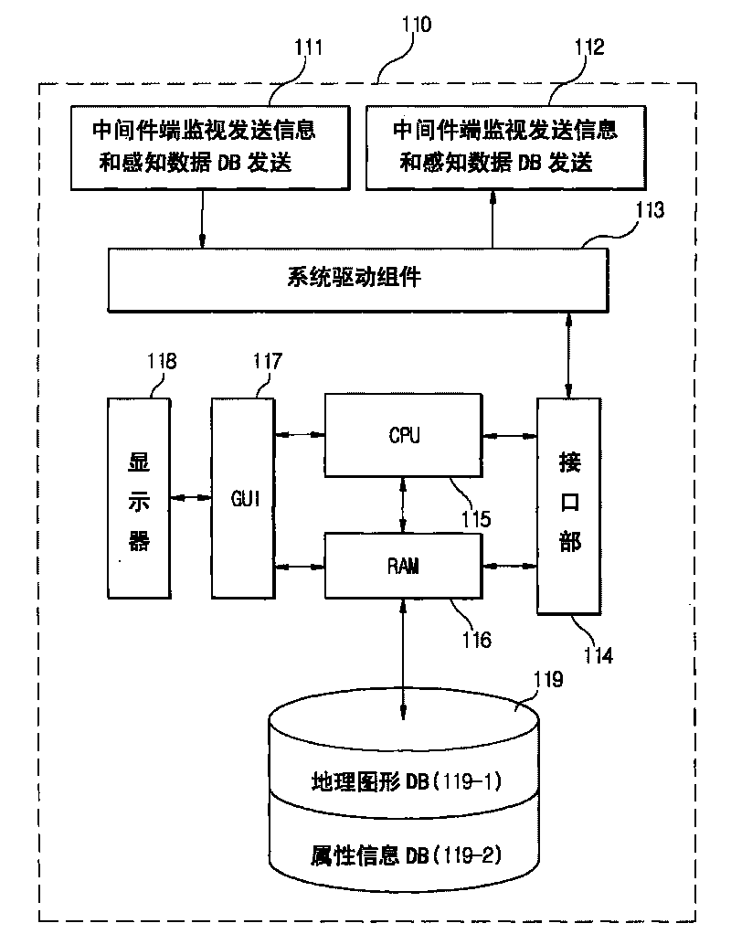
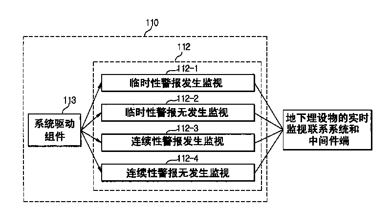
[0044] figure 1 It is a block diagram showing the interface structure of the real-time monitoring system of the ubiquitous base plate underground buried objects using GIS according to an embodiment of the present invention, figure 2 for figure 1 A structural diagram of the real-time monitoring system 110 for buried objects shown.

[0045]With reference to these drawings, the present invention relates to a system supported in such a manner that quick analysis of related information is possible through a basic database of buried objects constituting water and sewers, by observing Analysis, the pipes of the upper sewer and the sewer can quickly obtain information, and the real-time monitoring system of the buried objects can be used to register and manage the sensors directly installed on the upper sewer and the sewer. Information on the treatment of water and sewe...


PUM


Abstract

The invention aims at providing a real time monitoring system adopting a GIS (Graphical Information System) for the underground installation of a ubiquitous base plate. The underground installation can be effectively managed by rapidly acquiring the decision information of tubes of water supply pipelines and sewer by an observation and analysis technology for checking information to be input data. The system comprises a sensor, a sending part for sending information API and sensing data DB, a receiving part with a middle ware end receiving the information API and the sensing data DB, a system driving component, geographic graph DB including the graphical information of the underground installation of the water supply pipelines and the sewer and attribute information DB generated by the geographic graph DB, a GUI (Graphical User Interface) which is used for outputting images according to the result of the sensed value obtained through monitoring a setting process by the geographic graph DB and the attribute Information DB, and a central controlling and processing device which is electrically connected with and generally controls the DB, the system driving component and GUI.

Description

technical field [0001] The present invention relates to a real-time monitoring system for underground buried objects in a ubiquitous base plate using GIS. More specifically, the present invention relates to a basic database related to underground buried objects in waterways and sewers, which can quickly monitor related information. Analysis, the real-time monitoring system of underground buried objects can be used to register and manage the sensors directly installed on the waterways and sewers. By letting the sensors execute commands, the processing information of the waterways and sewers can be collected in real time and quickly. effective management of things. Background technique [0002] As is well known, people are actively developing information in multiple fields in real time through at least one main server through the medium of long-distance data communication network with the recent development of information communication technology. Information provision techno...

Claims


Application Information

Patent Timeline
IPC IPC(8): G05B19/048
Inventor 金桂炫
Owner 仁荷大学教产学协力团
Learn More