Dipole antenna of RF chip

A radio frequency chip and small antenna technology, applied in the field of wireless radio frequency devices, can solve problems such as difficult to meet the system design requirements of low power consumption, increase the design of electronic system feeders, increase the area of ​​radio frequency systems, etc., and achieve simple processing and low cost , the effect of enriching the dispersion characteristics

Active Publication Date: 2010-06-16
KUANG CHI INST OF ADVANCED TECH
View PDF4 Cites 210 Cited by
  • Summary
  • Abstract
  • Description
  • Claims
  • Application Information

AI Technical Summary

Problems solved by technology

However, the impedance matching network additionally increases the feeder design of the electronic system and increases the area of ​​the radio frequency system.

Method used


Image

  • Dipole antenna of RF chip
  • Dipole antenna of RF chip
  • Dipole antenna of RF chip

Examples


Embodiment 1

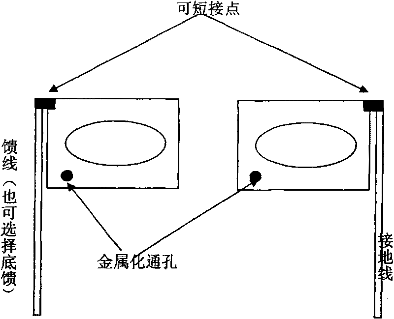
[0042] see figure 1 As shown in the topological structure, the small radio frequency chip antenna in this embodiment is composed of a feeder line, a ground line, and two metal sheets with a planar topological structure. Two metal sheets are placed in parallel, the feeder is fed into one of the metal sheets, the grounding wire is connected to the other metal sheet, and metallized through holes can be provided on the two metal sheets to realize the short connection of the metal sheets.

[0043] Among them, the feeder and the ground wire can generally be regarded as two pins of the small antenna of the RF chip, which are fed in with a standard 50 ohm impedance, but the feeding method of the feeder wire and the grounding method of the ground wire can be capacitive coupling or inductive coupling , specifically, there are four combinations of feeder feed-in mode and ground wire access mode, namely: feeder inductive feed-in, ground wire inductive grounding; feeder inductive feed-in, ...

Embodiment 2

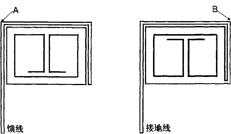
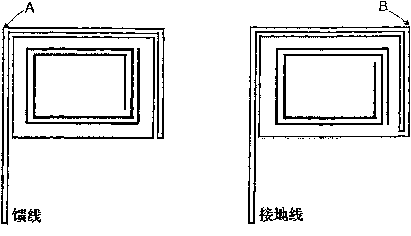
[0047] This embodiment utilizes the characteristics of artificial electromagnetic materials, adopts the method of engraving metal microstructures on the upper and lower metal sheets, so that the metal sheets are equivalently filled with an electromagnetic material with a dielectric constant according to the dispersion of the Lorentz material resonance model, so as to realize the change of the antenna. purpose of radiation properties.

[0048] see figure 2 , which gives a range of possible microstructures of equivalent electromagnetic materials, where, figure 2 (a) shows a schematic diagram of a small RF chip antenna engraved with a complementary split resonator ring structure; figure 2 (b) is a schematic diagram of a small radio frequency chip antenna with a complementary helical wire structure engraved; figure 2 (c) is a schematic diagram of a small radio frequency chip antenna engraved with an open spiral ring structure; figure 2 (d) is a schematic diagram of a small...


PUM


Abstract

The invention discloses a dipole antenna of an RF chip, comprising two metal sheets, a feeder line and an earth wire, wherein two tabulate metal sheets are mutually parallel and are both provided with short circuit points which are respectively used for connecting the feeder line and the earth wire. The dipole antenna of the RF chip of the invention integrates novel artificial electromagnetic materials, thus the dipole antenna has abundant chromatic dispersion characteristics so as to form various radioactive modes, which not only can avoid fussy impedance matching network, but also can tune by adjusting a feeder line feeding and coupling mode, an earth wire accessing mode, the topological structure of metal microstructure, the position of metalizing through holes as well as the short circuit point position among the feeder line, the earth wire, an upper layer of sheet metal and a lower layer of sheet metal, thus providing great convenience for multiple frequency point impedance matching; meanwhile, the dipole antenna of the invention adopts a chip mode to fully utilize radiating area to approach to the Chu Limit antenna dimension limit principle, the construction of double chips also brings technical advantages for limiting electromagnetic wave and reducing effect on antenna operation by the outside.

Description

technical field [0001] The invention relates to the technical field of wireless radio frequency devices, in particular to a novel small radio frequency chip antenna. Background technique [0002] With the high development of semiconductor technology, higher and higher requirements are put forward for the integration of today's electronic systems, and the miniaturization of devices has become a technical issue of great concern to the entire industry. However, unlike the development of IC chips following "Moore's Law", radio frequency modules, another important component of electronic systems, face the difficult technical challenge of device miniaturization. The radio frequency module mainly includes main components such as frequency mixing, power amplifier, filter, radio frequency signal transmission, matching network and antenna. Among them, the antenna is the radiating unit and receiving device of the final radio frequency signal, and its working characteristics will direc...

Claims


Application Information

Patent Timeline
IPC IPC(8): H01Q1/38H01Q13/10
Inventor 刘波
Owner KUANG CHI INST OF ADVANCED TECH
Why Eureka
Try Eureka