Support frame mechanism of scanning device

A technology of scanning device and support frame, which is applied in the direction of image communication, electrical components, etc., can solve the problems of replacement, increased cost, damage to scanning device, etc., and achieve the effect of convenient replacement of parts, cost saving and simple operation

Inactive Publication Date: 2010-06-16
PRIMAX ELECTRONICS LTD
View PDF0 Cites 1 Cited by
  • Summary
  • Abstract
  • Description
  • Claims
  • Application Information

AI Technical Summary

Problems solved by technology

[0005] Although the existing supporting frame structure 10 can support the upper cover 12 to make it convenient for the user to use the scanning device 1, when the upper cover 12 is opened and closed each time, the supporting frame 13 and the fixing part 14 collide with the base 11. Friction, after a long period of use, the support frame structure 10 will produce powder particles due to friction, and these powder particles will enter the interior of the scanning device 1, which will affect the scanning quality in light cases, or damage the scanning device in severe cases
In addition, the support frame 13 and the fixing part 14 will be deformed due to long-term friction, so that the fixing part 14 cannot be fixed on the base 11, and the support frame 13 is detached from the base 11, as figure 2 shown
In addition, since the supporting frame structure 10 is directly arranged on the scanning device, when the supporting frame structure 10 is worn, the part of the base 11 used to engage the fixing part 14 is also worn and needs to be replaced. At this time, not only the supporting frame structure 10 , even the base 11 must be replaced
Although such a support frame structure 10 brings convenience, after the support frame structure 10 wears for a long time, the result that both the support frame structure 10 and the base 11 need to be replaced increases the cost. Therefore, a method that can improve the existing Support frame structure with technical defects

Method used


Image

  • Support frame mechanism of scanning device
  • Support frame mechanism of scanning device
  • Support frame mechanism of scanning device

Examples


Embodiment Construction

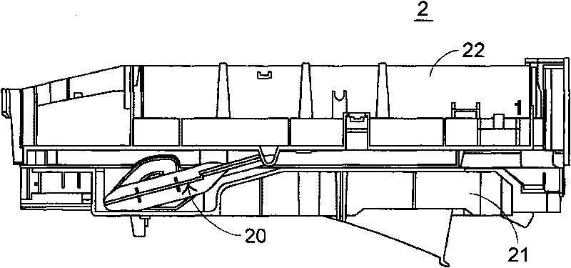
[0040] see image 3 , which is a schematic structural diagram of the support frame mechanism of the scanning device of the present invention in a closed state in a preferred embodiment. The scanning device 2 includes a base 21 and an upper cover 22, image 3 It is shown that the upper cover 22 covers the base 21, that is, the scanning device 2 is in a closed state.

[0041] see next Figure 4 , which is a partial structural exploded view of the support frame mechanism of the scanning device of the present invention in a preferred embodiment. The support frame structure 20 of the scanning device 2 includes a cam track 23 , a restraining piece 24 , a support frame 25 and a spring 26 . The cam track 23 is disposed on the base 21 and has an open position OP and a closed position CP on the cam track 23 . The restraining piece 24 is disposed in the cam track 23, and the restraining piece 24 has an inclined surface 241 and a blocking portion 242 (please refer to Image 6 ). One ...


PUM


Abstract

The invention relates to a support frame mechanism of a scanning device. The scanning device comprises a base and an upper cover, wherein the cover is pivoted on the base and is uncovered relative to a bottom cover. The support frame mechanism comprises a cam track, a check sheet, a support frame and a spring, wherein the support frame is arranged between the base and the upper cover; one end of the support frame is provided with a convex column and extends into the cam track, while the other end of the support frame is connected to the upper cover. When the convex column is positioned a closed position and the upper cover is uncovered, the convex column is blocked by the check sheet and slides in a first direction to an open position of the cam track; and the convex column is positioned the open position and the upper cover is uncovered, the convex column slides in the first direction to the closed position of the cam track through the check sheet. The support frame slides in the cam track to open or close the upper cover and supports the upper cover when opening, so that the support frame mechanism is simple in operation and structure, and saves the cost.

Description

technical field [0001] The invention relates to a scanning device, in particular to a support frame structure in the scanning device. Background technique [0002] With the progress of the times, the storage of data has been digitized, that is, the document data is scanned by a scanning device and converted into a digital format for storage, wherein the scanning device includes a scanner, a multifunction printer, or a printer. [0003] The earliest scanning device includes a base and an upper cover. The user lifts the upper cover to place the document on the base, and the scanning module disposed in the base scans the document to convert the document into an electronic file. However, every time a document is put in or taken out, the user must support the upper cover with his hands, so that there is an included angle between the base and the upper cover to facilitate putting in or taking out the document. Supporting the upper cover causes a little inconvenience, so a scannin...

Claims


Application Information

Patent Timeline
Patent Type & Authority Applications(China)
IPC IPC(8): H04N1/00
Inventor 汤锡添
Owner PRIMAX ELECTRONICS LTD
Why Eureka
Try Eureka