
Video encoding system and method, and control method and device for regulating code bit width

A technology of video encoding and video encoder, which is applied in the field of control, and can solve problems such as waste of resources, reduction of video encoding speed, waste of encoding speed of video encoder 12, etc.

Active Publication Date: 2010-06-16
VIMICRO ELECTRONICS CORP +1
View PDF0 Cites 7 Cited by
  • Summary
  • Abstract
  • Description
  • Claims
  • Application Information

AI Technical Summary

Problems solved by technology

[0008] For the above situation, if a fixed 10-bit encoding bit width is used, the dynamic range of brightness is only 2 10 The image data of , of course, can guarantee that it will not lose luminance details after encoding; however, the dynamic range of luminance is only 2 9 image data, obviously wastes the hardware resources of the video encoder 12, and obviously wastes the encoding speed of the video encoder 12 relative to the video encoding using 9-bit encoding bit width
[0009] It can be seen that since the existing video coding adopts a fixed coding bit width, and the coding bit width cannot be adjusted in real time according to the change of the brightness dynamic range, the dynamic range of the brightness is less than 2 N image data, if the encoding bit width of N bits is still used, it will cause a waste of resources and relatively reduce the video encoding speed

Method used


Image

  • Video encoding system and method, and control method and device for regulating code bit width
  • Video encoding system and method, and control method and device for regulating code bit width
  • Video encoding system and method, and control method and device for regulating code bit width

Examples


example 1

[0202] Assume that the number of image data output by the photosensitive device is N=10, and the image data includes M pixels in total, and M is a positive integer.

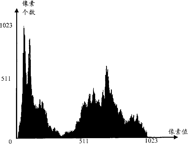
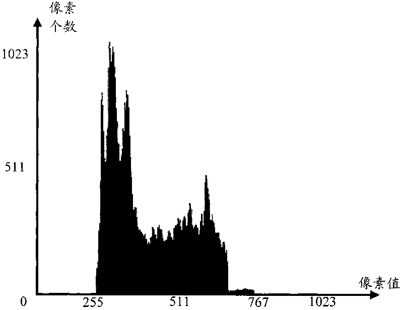
[0203] see Figure 5a , both the lower limit and the upper limit represent the brightness value interval. The first method divides 1024 pixel brightness values ​​from 0 to 1023 into 64 intervals, each interval contains 16 pixel brightness values, and then counts the brightness values ​​belonging to each interval The number of pixels S(j), 0≤j≤63, and j is a positive integer, then in the detected histogram, the lower limit Min and upper limit Max representing the brightness value interval should satisfy respectively:

[0204] and α is the preset first scaling factor, which is preferably 1% to 5% in this embodiment;

[0205] and β is a preset second scaling factor, preferably 1%-5% in this embodiment.

[0206] Then, assume that α and β both take 1% (α and β can also be different), that is, the sum of the ...

example 2

[0215] Assume that the number of image data output by the photosensitive device is N=10, and the image data includes M pixels in total, and M is a positive integer.

[0216] see Figure 6a , both the lower limit and the upper limit represent the pixel brightness value in the second way, divide the 1024 pixel brightness values ​​from 0 to 1023 into 1024 intervals, that is, there is only one pixel brightness value i in each interval, 0≤i≤2 10 -1, and i is a positive integer, then the detected lower limit Min and upper limit Max of the pixel brightness value in the histogram both represent specific pixel brightness values, and satisfy respectively:

[0217] and α is the preset first scaling factor, which is preferably 1% to 5% in this embodiment;

[0218] and β is a preset second proportional factor, preferably 1% to 5% in this embodiment;

[0219] Wherein, H[i] represents the number of pixels whose brightness value is i in the histogram.

[0220] Then, assume that α a...


PUM


Abstract

The invention discloses a video encoding system, a video encoding method and a control device and a control method for regulating code bit width. The video encoding method comprises the following steps of: detecting an upper limit and a lower limit of a pixel brightness value according to a column diagram of image data; determining the code bit width practically needed by the image data accordingto a brightness dynamic range of the image data represented by a pixel brightness value range between the upper limit and the lower limit; allowing a video encoder to subtract a value of a brightnessoffset parameter from all pixel values of the image data by using the calculated code bit width as a value of a code bit width parameter of a video encoder, regulating the code bit width of the videoencoder and using the detected lower limit of the pixel brightness as the value of the brightness offset parameter of the video encoder; and directly acquiring a corresponding low bit from the image data, namely, performing video encoding on the image data by using the value of the code bit width parameter as the code bit width. Therefore, the waste of hardware resources and the reduction in the encoding speed are avoided.

Description

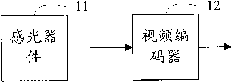
technical field [0001] The present invention relates to control technology, in particular to a video encoding system capable of adjusting encoding bit width, a video encoding method, a control device for adjusting encoding bit width, and a control method for adjusting encoding bit width. Background technique [0002] In the field of video surveillance, it is necessary to perform video encoding on captured image data and then transmit it. figure 1 It is a schematic structural diagram of an existing video coding system. Such as figure 1 As shown, the system includes a photosensitive device 11 and a video encoder 12 . [0003] The photosensitive device 11 outputs N-bit image data to the video encoder 12; in order to ensure that the brightness dynamic range of the image data will not be reduced after encoding, so as to avoid the loss of various brightness details in the image data, the video encoder 12 uses N-bit encoding The bit width performs video encoding on the received ...

Claims


Application Information

Patent Timeline
IPC IPC(8): H04N7/26H04N19/136
Inventor 王浩邱嵩杨晓东
Owner VIMICRO ELECTRONICS CORP
Learn More