Floor structure for vehicle body

A body floor and structure technology, which is applied to the superstructure, vehicle components, superstructure sub-assemblies, etc., to achieve the effect of improving ride comfort and suppressing up and down vibrations

Inactive Publication Date: 2012-06-20
HONDA MOTOR CO LTD
View PDF1 Cites 0 Cited by
  • Summary
  • Abstract
  • Description
  • Claims
  • Application Information

AI Technical Summary

Problems solved by technology

[0011] As a result, in Figure 10 In (a), when the floor 121 vibrates up and down along with the vertical vibration of the vehicle body, the floor 121 is likely to start from the junction of the tunnel portion 122 and the front side beam 126, and the junction of the tunnel portion 122 and the inner side beam 128. Vibrate sharply in the way of bending as indicated by the arrow

Method used


Image

  • Floor structure for vehicle body
  • Floor structure for vehicle body
  • Floor structure for vehicle body

Examples


Embodiment Construction

[0052] Embodiments of the present invention will be described below with reference to the accompanying drawings. Wherein, the drawings are viewed from the direction of the reference numerals.

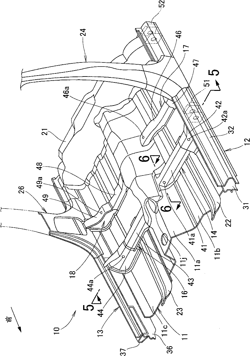
[0053] figure 1 It is a perspective view showing the underbody of the underbody structure of the present invention, and the arrow (FRONT) in the figure indicates the front of the vehicle having the underbody (the same applies hereinafter).

[0054]The bottom vehicle body 10 includes: a front floor 11; side beams 12, 13 installed on both ends of the front floor 11 so as to extend in the front-rear direction of the vehicle body; The tunnel portion 11a at the center of the vehicle width direction of the floor panel 11, and a pair of first beams 14, 16 and a pair of second beams 17, 18 connecting the side rails 12, 13 to the left and right respectively; And be installed on the middle floor beam 21 of the rear end of the front floor 11; The front floor member 22,23 on the both sides of th...


PUM


Abstract

The invention provides a floor structure for vehicle body capable of inhibiting the vertical shock of the floor. a channel part (11a) extended back and forth is formed on the middle on the front floor (11); side bar inner parts (31, 36) having side bars extended back and forth are mounted on the left and right end of the front floor (11); and the channel part (11a) and the side bar inner parts are connected by first crossbeams (14, 16); the first crossbeam is extended on the front floor (11) along the vehicle width direction, step parts (11j, 11k) are formed on the channel part (11a); an in-channel crossbeam (48) inside the channel in the channel part (11a) and he first crossbeams (14, 16) on the front floor (11) are combined linearly by the step parts (11j, 11k).

Description

technical field [0001] The present invention relates to improvements in underbody construction. Background technique [0002] As a conventional underbody structure, there is known a structure including a seat bracket extending in the vehicle width direction on the floor for attaching a seat (for example, refer to Patent Document 1). [0003] Patent Document 1: Japanese Unexamined Patent Application Publication No. 2006-82720 [0004] with the following Figure 8 to Patent Document 1 figure 1 Be explained. Here, the reference signs have been converted. [0005] Figure 8 It is a perspective view showing main parts of a conventional underbody structure. A floor 101 includes a center tunnel 102 extending front and rear in the center of the vehicle width direction, and floor portions 103, 103 provided on the left and right sides of the center tunnel 102. The floor portions 103, 103 rear As the seat installation position 104 , rear end portions of the floor portions 103 , 10...

Claims


Application Information

Patent Timeline
Patent Type & Authority Patents(China)
IPC IPC(8): B62D25/20
CPCB62D25/025B62D25/20B62D25/2036
Inventor 松山升平
Owner HONDA MOTOR CO LTD
Why Eureka
Try Eureka