Thread tension device

A tensioning device, yarn technology, applied in the direction of transportation and packaging, thin material handling, conveying filamentous materials, etc., can solve problems and other problems

Active Publication Date: 2010-06-23
KARL MAYER STOLL R&D GMBH
View PDF1 Cites 2 Cited by
  • Summary
  • Abstract
  • Description
  • Claims
  • Application Information

AI Technical Summary

Problems solved by technology

This can cause bobbins that work well with one yarn to have problems with another

Method used


Image

  • Thread tension device
  • Thread tension device
  • Thread tension device

Examples


Embodiment Construction

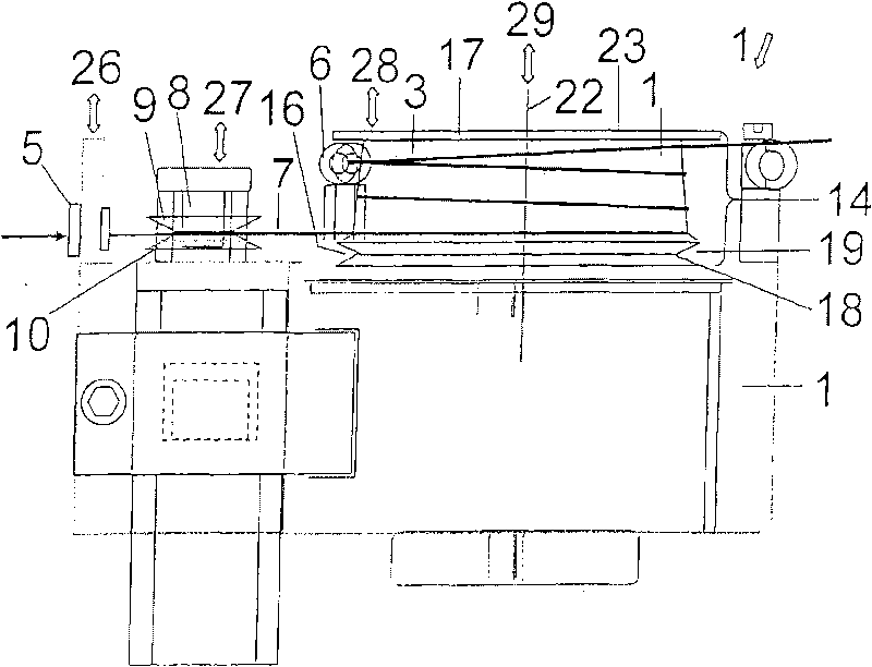
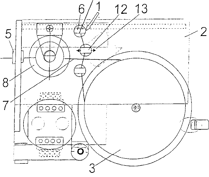
[0021] figure 1 The yarn tensioning device 1 is shown, which has a base 2 on which the bobbin 3 is rotatably supported. The bobbin 3 can be connected to the motor 4 in a torsion-resistant manner, and the motor 4 can also be operated by a generator.

[0022] The base 2 is provided with a lead-in part 5 and a lead-out part 5.

[0023] The yarn 7 passes through the lead-in 5 and is wound around the bobbin 3, and then passes through the lead-out 6. A stabilizing device 8 is provided between the lead-in 5 and the bobbin 3, which consists of two discs 9, 10 designed in a conical shape, which are stacked on top of each other with their smaller diameters. The stabilizing device 8 attenuates vibrations in the yarn 7, which may be caused, for example, by drawing the yarn 7 through the head from a loop not shown in detail.

[0024] A yarn guide 11 with a movable yarn guide 12 is arranged between the bobbin 3 and the lead-out member 6. The yarn guide 12 can move in the direction of the double ...


PUM


Abstract

The device (1) has a thread drum (3) arranged between an inlet guide (5) and an outlet guide (6) and provided with a rotation axis (22) and a work area (14). A thread path runs between the inlet guide (5) and the outlet guide (6) on the work area in a circumferential direction. The work area is divided into sections (15, 16) in an axial direction, where the sections exhibit different characteristics for combining high flexibility and low time consumptioin.

Description

Technical field [0001] The invention relates to a yarn tensioning device, which has an introduction part, a withdrawal part and a bobbin located between them. The bobbin has a rotating shaft and a working area. The yarn path between the introduction part and the withdrawal part is The working area extends in the circumferential direction. Background technique [0002] Such a yarn tensioning device is disclosed, for example, by DE 43 24 412 A1. It is used to tension the yarn drawn from the loops placed in the creel, and the yarn needs to be tensioned in the next further processing. To this end, the bobbin can be braked or driven at a different speed than the yarn, for example. When the yarn passes through the yarn path, it will abut on the bobbin in the working area and be braked or accelerated accordingly to obtain the desired tension in the yarn. [0003] Different yarns usually have different characteristics. This can lead to problems with bobbins that work well with one type...

Claims


Application Information

Patent Timeline
IPC IPC(8): B65H59/38B65H57/00
CPCB65H2701/31B65H59/16B65H59/14
Inventor M·富尔
Owner KARL MAYER STOLL R&D GMBH
Why Eureka
Try Eureka