Thread tension device

A tensioning device, yarn technology, used in transportation and packaging, thin material handling, transportation of filamentous materials, etc., can solve problems such as problems

Active Publication Date: 2012-09-26
KARL MAYER STOLL R&D GMBH
View PDF1 Cites 0 Cited by
  • Summary
  • Abstract
  • Description
  • Claims
  • Application Information

AI Technical Summary

Problems solved by technology

This can cause bobbins that work well with one yarn to have problems with another

Method used


Image

  • Thread tension device
  • Thread tension device
  • Thread tension device

Examples


Embodiment Construction

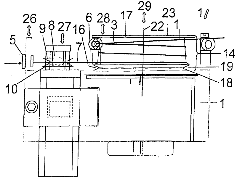
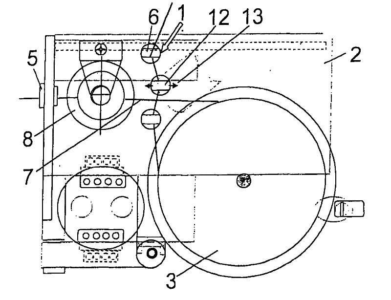
[0021] figure 1 A yarn tensioning device 1 is shown, which has a base 2 on which a bobbin 3 is rotatably mounted. The bobbin 3 can be connected in a rotationally fixed manner to an electric motor 4 which can also be operated as a generator.

[0022] On the base 2 there are lead-in parts 5 and lead-out parts 5 .

[0023] The yarn 7 is passed through the inlet 5 and wound around the bobbin 3 and then through the outlet 6 . Between the insertion part 5 and the bobbin 3 there is a securing device 8 which consists of two conically shaped disks 9 , 10 which are placed one above the other with their smaller diameters. The stabilizing device 8 dampens vibrations in the yarn 7 which may be caused, for example, by withdrawing the yarn 7 through the head from the coil, which is not shown in detail.

[0024] Arranged between the bobbin 3 and the withdrawal part 6 is a yarn guide 11 with a movable yarn guide 12 which is movable in the direction of the double arrow 13 , that is to say su...


PUM


Abstract

The device (1) has a thread drum (3) arranged between an inlet guide (5) and an outlet guide (6) and provided with a rotation axis (22) and a work area (14). A thread path runs between the inlet guide (5) and the outlet guide (6) on the work area in a circumferential direction. The work area is divided into sections (15, 16) in an axial direction, where the sections exhibit different characteristics for combining high flexibility and low time consumptioin.

Description

technical field [0001] The invention relates to a yarn tensioning device with an inlet, an outlet and a bobbin between them, the drum having a rotation axis and a working area, the yarn travels between the inlet and the outlet in the The working area extends circumferentially. Background technique [0002] Such a thread tensioning device is known, for example, from DE 43 24 412 A 1. It is used to tension the yarn drawn from the coil placed in the creel, which needs to be tensioned in the following further processing. For this purpose, the bobbin can eg be braked or driven at a different speed than the yarn. As the yarn passes through the yarn path, it rests against the bobbin in the working area and is braked or accelerated accordingly, so that the desired tension is achieved in the yarn. [0003] Different yarns often also have different properties. This can lead to bobbins that work well with one yarn to have problems with another. The spools are therefore designed to...

Claims


Application Information

Patent Timeline
Patent Type & Authority Patents(China)
IPC IPC(8): B65H59/38B65H57/00
CPCB65H2701/31B65H59/16B65H59/14
Inventor M・富尔
Owner KARL MAYER STOLL R&D GMBH
Why Eureka
Try Eureka