Peristaltic micro-irrigation emitter
A water device and micro technology, applied in watering devices, fluid flow, gardening, etc., can solve the problem of easy loss of irrigation uniformity, and achieve the effects of excellent anti-clogging performance, increased flow cross-section, and excellent irrigation uniformity.
- Summary
- Abstract
- Description
- Claims
- Application Information
AI Technical Summary
Problems solved by technology
Method used
Image

Examples
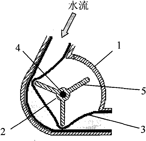
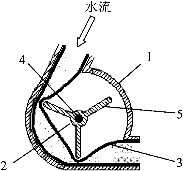
Embodiment 1
[0012] refer to figure 1 The main structure of the peristaltic micro-irrigation emitter is composed of the shell 1, the runner 2, the fine elastic hose 3, the runner blade 5 and the rotating shaft 4. The fine hose, runner and shaft are all packaged in the casing, and the blades on the runner press on the hose, making the partial section of the hose flat. The water flows in from one end of the hose, pushes the blades, and drives the runner to rotate. With the rotation of the runner, the blades periodically press the hose, and the hose is squeezed and released alternately, so that the water flows in a peristaltic state, and finally flows out from the other end of the hose, thereby obtaining a strong solidification transport capacity. The required emitter flow rate can be obtained by changing the diameter of the hose and the rotation speed of the runner, and good irrigation uniformity can be obtained by controlling the rotation uniformity of the runner.
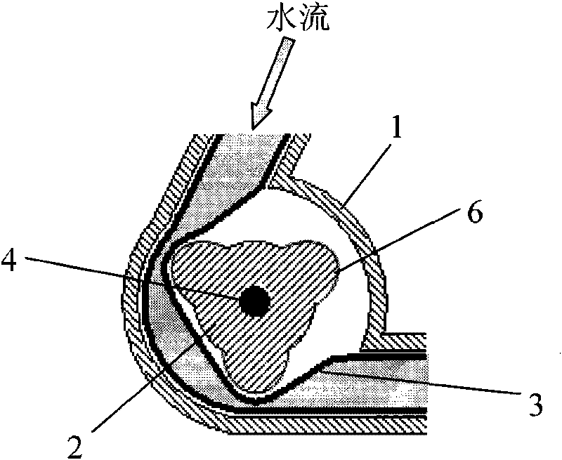
Embodiment 2
[0014] refer to figure 2 The main structure of the peristaltic micro-irrigation emitter is composed of the shell 1, the runner 2, the fine elastic hose 3, the runner protrusion 6, and the rotating shaft 4. The tiny hose, the runner and the rotating shaft are all packaged in the housing, and the protrusions on the runner press on the hose, making the partial section of the hose flat. The water flows in from one end of the hose, pushes the blades, and drives the runner to rotate. With the rotation of the runner, the protrusions on the runner periodically press the hose, and the hose is squeezed and released alternately, so that the water flows out from the other end of the hose in a peristaltic state, forming a peristaltic flow, thus obtaining a strong solidified transport capacity. The required emitter flow rate can be obtained by changing the diameter of the hose and the rotation speed of the runner, and good irrigation uniformity can be obtained by controlling the rotation...
PUM
 Abstract
Description
Claims
Application Information