Irrigation device for densely planted crops

An irrigator and irrigation technology, applied in the fields of botanical equipment and methods, watering devices, gardening, etc., can solve the problems of small flow, difficult to control operation, limited water infiltration range, etc., and achieve the effect of slowing down the water flow and preventing clogging. Good, the effect of shortening the irrigation time

Active Publication Date: 2017-04-12
JIANGSU HUAYUAN IRRIGATION & DRAINAGE
View PDF4 Cites 0 Cited by
  • Summary
  • Abstract
  • Description
  • Claims
  • Application Information

AI Technical Summary

Problems solved by technology

During irrigation, the water flow enters the flow channel and directly enters the labyrinth, which not only has poor energy dissipation and flow stabilization effects, but also tends to block the labyrinth after continuous sediment deposition; during irrigation intervals, the drip irrigation channel / belt and muddy water outside the emitter Under the action of negative pressure, it will recharge through the drip outlet, blocking the water outlet or the labyrinth close to the water outlet
Due to the small size of the flow channel diameter and the complex structure of the flow channel, it is difficult to wash away the blocked part with water flow, and it is very difficult to clean the flow channel, which makes the entire irrigation system unable to work; these labyrinth flow channels are axially arranged, The length is longer, generally 80-400 mm, the distance between the water outlets is relatively large, and the flow rate is relatively small, the infiltration range of the water flow is limited, and it is difficult to achieve precise irrigation for densely planted crops; the energy dissipation effect of the above-mentioned labyrinth flow channel The water pressure loss at the end of the maze has been relatively large, and the flow rate is relatively small, generally no more than 4 liters per hour. For crops that require a large amount of water, the dripping volume cannot meet the requirements; if the head is increased to increase the water output at the end of the maze Pressure, when the drip volume increases to 4 liters per hour or higher, because the diameter of the above-mentioned flow channel is small and the wall thickness is thin, the bonding strength between the flow channel wall and the drip irrigation channel / belt and emitter wall is low, and the pressure is too large. The phenomenon of flow channel rupture and water spraying at the water outlet can not achieve the purpose of water saving, so people urgently need large-flow drip irrigation channels / belts and emitters suitable for market demand for drip irrigation
[0003] However, if the flow rate of the drip irrigation channel / belt and the emitter is large, there will be problems such as the inconsistency between the flow rate and the area of ​​the irrigation area, and more system control valves, which will make the operation flow of the drip irrigation system confusing and the uniformity of irrigation water difficult to guarantee. Therefore, people generally It is believed that the product structure of the large-flow drip irrigation channel / belt and the emitter is complex, difficult to produce, difficult to control the operation, and unable to achieve the purpose of precision irrigation

Method used


Image

  • Irrigation device for densely planted crops
  • Irrigation device for densely planted crops
  • Irrigation device for densely planted crops

Examples


Embodiment 1

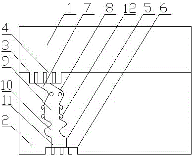
[0042] Such as figure 1 As shown, the emitter includes a water delivery chamber 1 and a water delivery chamber 2 sequentially extruded and vacuum formed along the inner surface of the water delivery chamber 1. The diameter of the water delivery chamber 1 is smaller than that of the irrigation chamber 2, and the water delivery chamber 2 is provided with an irrigation flow channel. 3. The water irrigation channel 3 is provided with four water inlets 4, energy dissipation and steady flow channels 5 and four water outlets 6. The water delivery chamber 1 communicates with the irrigation channel 3 through the water inlet 4, and the water outlet 6 communicates with the water irrigation channel 3. The energy-dissipating and steady-flow channel 5 is arranged radially along the irrigation chamber 2 and is composed of a water inlet section 7, a centrifugal section 8, a sedimentation section 9, an energy-dissipating section 10, and a water outlet section 11. The water inlet section 7. Cen...

Embodiment 2

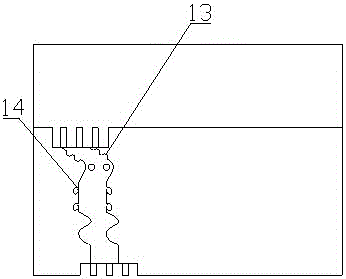
[0044] Such as figure 2 As shown, the difference from Embodiment 1 is that a sedimentation tank 13 is provided on the water inlet section 7, and the concave surface of the sedimentation tank 13 faces the inside of the energy dissipation and steady flow channel 5. When the water flow passes through the water inlet section 7, part of the mud The sand is deposited and deposited in the groove of the sedimentation tank 13, so that the cross-sectional area of ​​the water inlet section 7 can not be reduced, so that the energy dissipation steady flow channel 5 can not be blocked; the opening 14 of the collection chamber 12 It is funnel-shaped, that is, the size of the side toward the flow path of the deposition section 9 is larger than the size of the side toward the inside of the collection chamber 12, which not only facilitates the entry of sediment into the collection chamber 12, but also The sediment is not easy to come out from the inside, and the anti-clogging effect is better....

Embodiment 3

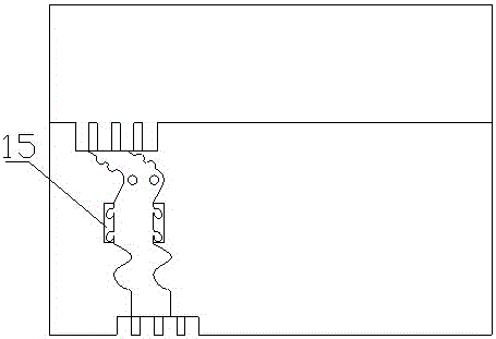
[0046] Such as image 3 As shown, the difference from Embodiment 1 is that a closed air pressure chamber 15 is provided at a position corresponding to the deposition section 9 in the irrigation chamber 2, and the air pressure chamber 15 is under negative pressure, and the air pressure chamber 15 connects the collection chamber 12 The outside is closed, and under the action of negative pressure, the collection chamber 12 is always kept open, which is more conducive to the deposition of sediment.


PUM


Abstract

The invention provides a specific-purpose irrigation emitter for close-planting crops. The irrigation emitter includes a water transportation cavity and irrigation cavities. The irrigation cavityis molded through successive vacuum formingalong the inner surface of the water transportation cavity. The irrigation cavity is provided with an irrigation flow channel therein. The irrigation flow channel is provided with a water inlet opening and a water outlet opening. The water transportation cavity is communicated with the irrigation flow channel via the water inlet opening. The irrigation flow channel includes a water inlet section which is constituted by an inclined flow channel, a centrifugal section which is provided with a helical centrifugal column, a deposition section which extends radially, an energy dissipation section which is constituted by a continuous S-shaped or corrugated flow channel, and a water outlet section which extends radiallywhich are successively connected. The specific irrigation emitter for high density planting of the invention is simple in structure, large in flow amount, not easily broken, and excellent in anti-clogging effect, and is applicable to precise irrigation for close-planting crops.

Description

technical field [0001] The invention relates to an irrigator for densely planted crops, in particular to a large-flow irrigator suitable for densely planted crops in large fields, and belongs to the technical field of water-saving irrigation agricultural equipment. Background technique [0002] Various drip irrigation channels / belts and emitters currently used in the field of agricultural micro-irrigation technology are provided with a set of labyrinth channels at the front of each drip outlet to damp and reduce the drip irrigation channels / belts and emitters. Balance the water pressure and water output of each drip outlet, so as to ensure that the water output of each drip outlet within a certain laying length of the drip irrigation channel / belt and emitter is basically the same. The labyrinth flow channel is roughly divided into two categories, one is formed separately, and then embedded in the drip irrigation channel / belt, emitter, or plugged outside the drip irrigation c...

Claims


Application Information

Patent Timeline
Patent Type & Authority Patents(China)
IPC IPC(8): A01G25/02
CPCA01G25/023
Inventor 尹飞虎何帅谢海霞
Owner JIANGSU HUAYUAN IRRIGATION & DRAINAGE
Why Eureka
Try Eureka