Electronic device with magnetic supporting foot rack

A technology of electronic devices and supporting feet, applied in the direction of machine/stand, supporting machine, electrical digital data processing, etc.

Active Publication Date: 2010-06-23
ASUSTEK COMPUTER INC
View PDF0 Cites 20 Cited by
  • Summary
  • Abstract
  • Description
  • Claims
  • Application Information

AI Technical Summary

Problems solved by technology

[0006] The purpose of the present invention is to overcome the defects of the existing electronic devices with supporting legs, and provide a novel structure of electronic d

Method used


Image

  • Electronic device with magnetic supporting foot rack
  • Electronic device with magnetic supporting foot rack
  • Electronic device with magnetic supporting foot rack

Examples


Embodiment Construction

[0029] In order to further explain the technical means and effects of the present invention to achieve the intended purpose of the invention, the specific implementation, structure, and structure of the electronic device with a magnetic support stand proposed in accordance with the present invention will be given below with reference to the accompanying drawings and preferred embodiments. The characteristics and effects are described in detail later.

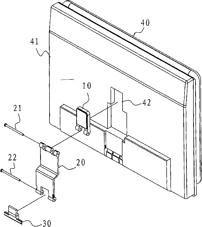
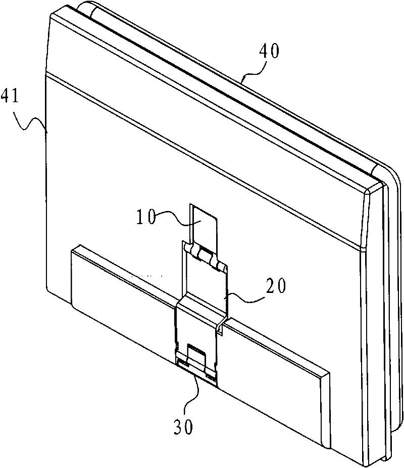
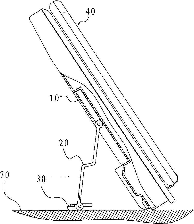
[0030] According to the electronic device with the magnetic supporting stand disclosed in the present invention, please refer to figure 1 , figure 2 As shown, it is an exploded and assembled schematic diagram of an electronic device with a magnetic supporting stand according to the present invention.

[0031] The electronic device with a magnetic supporting stand according to the present invention includes an electronic device body 40 and a magnetic supporting stand, and the magnetic supporting stand includes a magnetic element 10, a...


PUM


Abstract

The invention relates to an electronic device with a magnetic supporting foot rack, which comprises an electronic device machine body and the magnetic supporting foot rack. The magnetic supporting foot rack comprises a magnetic element, a connecting rod and a foot rack. The magnetic element is absorbed at the back face of the electronic device machine body, one end of the connecting rod is pivoted at the magnetic element, and the foot rack is pivoted at the other end of the connecting rod. Under the function of the connecting rod, the foot rack is placed at the storing position at the back face of the electronic device machine body; under the function of the linkage of the connecting rod, the foot rack is stretched to the supporting position that can support the electronic device machine body; when the foot rack is placed at the supporting device and the load of the electronic device is over high, the magnetic element can be separated from the electronic device machine body so as to prevent the foot rack and the connecting rod from being permanently damaged.

Description

Technical field [0001] The present invention relates to an electronic device with a magnetic supporting foot stand. For example, a supporting foot stand is added to an electronic device such as a notebook computer and a tablet computer. In particular, it relates to a magnetic supporting foot stand that utilizes magnetic elements to be adsorbed to the electronic device. Background technique [0002] In order to match the user's operating habits, electronic devices such as notebook computers or tablet computers can be designed with a tripod to provide support for the electronic device from different angles, which can satisfy the user's operational convenience. The most common operating angles can be summarized as high angles (about 70 to 80 degrees), medium angles (about 40 to 60 degrees), and low angles (about 20 to 35 degrees). At a high angle, it can be used as an electronic digital photo frame or stock machine; at a medium angle, it can be adjusted to the appropriate angle when...

Claims


Application Information

Patent Timeline
IPC IPC(8): G06F1/16F16M11/00
Inventor 邱显成陈振宏杨孟儒廖志诚
Owner ASUSTEK COMPUTER INC
Why Eureka
Try Eureka