Uninterruptible power supply provider

A technology of power supply and power control circuit, which is applied in current collectors, battery circuit devices, electric vehicles, etc. It can solve the problems of power consumption, failure of silicon-controlled rectifier cut-off, and reduced efficiency of uninterruptible power supply, so as to prevent startup The effect of excessive current

Active Publication Date: 2010-06-23
DELTA ELECTRONICS INC
View PDF0 Cites 8 Cited by
  • Summary
  • Abstract
  • Description
  • Claims
  • Application Information

AI Technical Summary

Problems solved by technology

[0008] However, although the thermistor can reduce the start-up current, it also consumes unnecessary power, which reduces the overall efficiency of the UPS
Furthermore, the resistance value of the thermistor needs to be properly adjusted according to the capacitance value of the bus capacitor. However, the bus capacitor generally uses an electrolytic capacitor with a large capacitance error. The error value of the bus capacitor makes the actual capacitance value of the bus capacitor not correspond to the thermistor with the appropriate resistance value, so the thermistor cannot effectively reduce the startup current
[0009] In addition, the phase adjustment circuit can only adjust the phase of the AC input voltage transmitted to the AC-DC conversion circuit, and cannot control the magnitude of the input current when the phase is turned on. The magnitude of the current when the phase is turned on changes with the voltage value of the AC input voltage , and the phase adjustment circuit composed of the silicon controlled rectifier cannot cut off the silicon controlled rectifier of the phase adjustment circuit through the phase control circuit after the silicon controlled rectifier is turned on, so the starting current cannot be accurately reduced
However, the complexity of the phase control circuit is high, which makes the stability of the phase control circuit relatively low, which in turn causes the overall stability of the uninterruptible power supply to be low.

Method used


Image

  • Uninterruptible power supply provider
  • Uninterruptible power supply provider
  • Uninterruptible power supply provider

Examples


Embodiment Construction

[0052] Some typical embodiments embodying the features and advantages of the present invention will be described in detail in the description in the following paragraphs. It should be understood that the invention is capable of various changes in different forms without departing from the scope of the invention, and that the description and drawings therein are illustrative in nature and not limiting. invention.

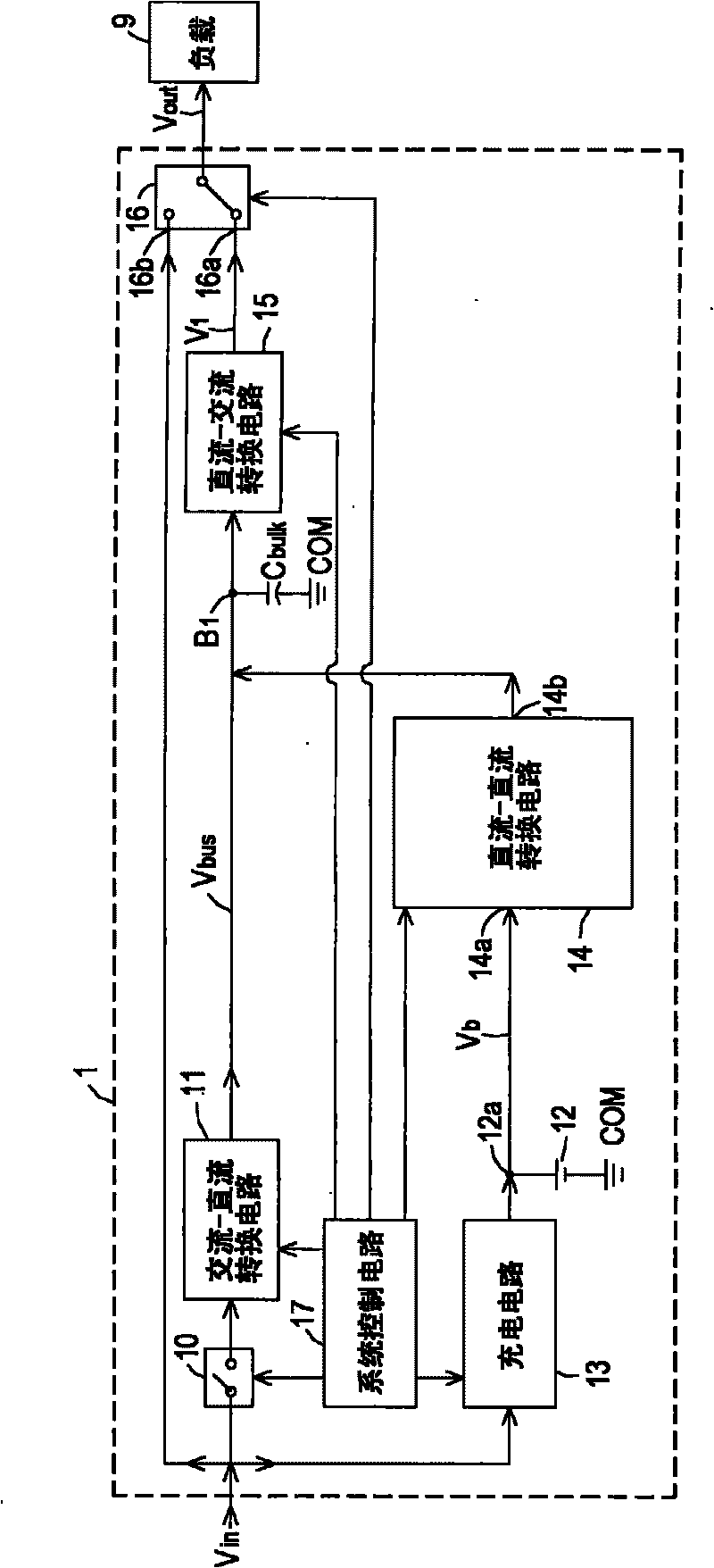
[0053] see figure 1 , which is a schematic block diagram of a circuit of an uninterruptible power supply according to a preferred embodiment of the present invention. Such as figure 1 As shown, the uninterruptible power supply 1 of the present invention can receive the AC input voltage V in , and generate a stable and uninterrupted AC output voltage V out To supply power to the load 9 for use. In addition, when the AC input voltage V in When unstable, such as when abnormality or interruption occurs, the uninterruptible power supply 1 of the present invention ca...


PUM


Abstract

The invention relates to an uninterruptible power supply provider, which comprises an input switch circuit, an AC-DC conversion circuit, a bus capacitor, an energy storage unit, a charging circuit, a DC-AC conversion circuit and a system control circuit, wherein the AC-DC conversion circuit is connected between the input switch circuit and a direct current bus, the bus capacitor is connected with the direct current bus, the energy storage unit is selectively connected with a connecting end and a common connecting end of the energy storage unit, the charging circuit is connected with the input switch circuit and the connecting end of the energy storage unit, the DC-AC conversion circuit is connected with the connecting end of the energy storage unit and the direct current bus, and the system control circuit is connected with the input switch circuit, the AC-DC conversion circuit, the charging circuit and the DC-AC conversion circuit to be used for controlling operation and controls the AC-DC conversion circuit to stop operation when the uninterruptible power provider starts so as to enable the DC-AC conversion circuit to charge the bus capacitor. According to the invention, the condition that impact currents exist in the uninterruptible power provider because of overlarge start currents of the uninterruptible power provider can be prevented from occurring.

Description

technical field [0001] The present invention relates to a power supply, in particular to an Uninterruptible Power Supply (UPS). Background technique [0002] With the rapid development of information industry and high-tech industry, most precision electronic instruments and equipment need to rely on high-quality power supply to maintain normal operation. Among various power supply methods, the UPS can not only ensure that the power will not be interrupted, but also provide high-quality power, so the UPS has become the best solution for providing high-quality power today. [0003] A traditional uninterruptible power supply includes an AC-DC conversion circuit, a DC-AC conversion circuit, and a bus capacitor, wherein the output end of the AC-DC conversion circuit is connected to the bus capacitor and the input end of the DC-AC conversion circuit to convert the AC The input voltage is converted to a DC voltage and a bus voltage is generated on the DC bus, and the bus capacitor...

Claims


Application Information

Patent Timeline
Patent Type & Authority Applications(China)
IPC IPC(8): H02J7/00
Inventor 赖渊芳
Owner DELTA ELECTRONICS INC
Why Eureka
Try Eureka