Protective device of boost converter

A technology of boost converter and protection device, applied in the field of boost converter

Inactive Publication Date: 2010-06-23
RICHTEK TECH
View PDF5 Cites 6 Cited by
  • Summary
  • Abstract
  • Description
  • Claims
  • Application Information

AI Technical Summary

Problems solved by technology

[0004] Therefore, there are above-mentioned inconv

Method used


Image

  • Protective device of boost converter
  • Protective device of boost converter
  • Protective device of boost converter

Examples


Embodiment Construction

[0092] The present invention will be further described below in conjunction with embodiment and accompanying drawing.

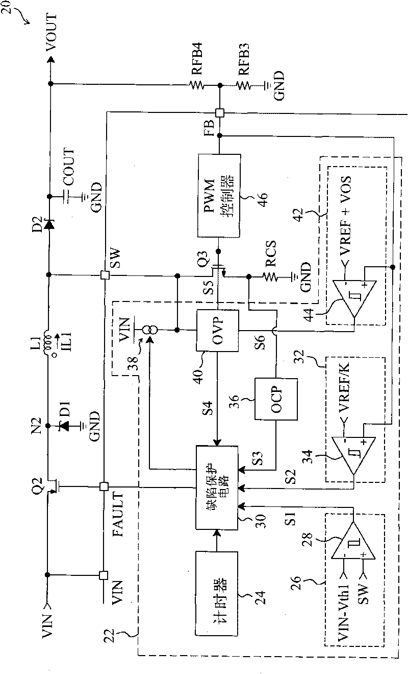
[0093] see now image 3 , image 3A schematic diagram of an embodiment of the invention is shown. As shown in the figure, in the boost converter 20, the load cut-off switch Q2 is connected between the input terminal VIN and the node N2, the inductor L1 is connected between the node N2 and SW, and the diode D2 is connected between the node SW and the output terminal VOUT Between, the capacitor COUT is connected to the output terminal VOUT, the power switch Q3 is connected between the node SW and the ground terminal GND, the resistors RFB3 and RFB4 divide the output voltage VOUT, and the resistor RFB3 is connected between the feedback terminal FB and the ground terminal GND, The resistor RFB4 is connected between the output terminal VOUT and the feedback terminal FB, the PWM controller 46 switches the power switch Q3 according to the voltage on the feedback t...


PUM


Abstract

The present invention relates to a protective device of a boost converter. The boost converter comprises an inductance connected between a first node and a second node, a first switch connected between the input end of the boost converter and the first node, a second switch connected between the second node and a grounding end, and a boost connected between the second node and the output end of the boost converter. The protective device comprises an overvoltage protective circuit, a defect protective circuit and a current source. The protective device is characterized in that the overvoltage protective circuit is connected with the second node; when voltage on the second node is larger than a first threshold value, a first signal and a second signal are generated; the second signal is used for opening the second switch and discharging to the second node; the detect protective circuit is used for closing the first switch according to the first signal; the current source is connected with the second node to provide an advanced charging current to charge the second node after the first switch is closed.

Description

technical field [0001] The invention relates to a boost converter, in particular to a protection device and method for a boost converter. Background technique [0002] figure 1 A conventional boost converter 10 is shown, which includes a load cut-off switch Q1 connected between the input terminal VIN and the inductor L, a diode D1 connected between the inductor L and the output terminal VOUT, and a power switch 12 connected between the node N1 and the ground terminal GND Between, the capacitor COUT is connected to the output terminal VOUT, and the resistors RFB1 and RFB2 divide the output voltage VOUT, wherein the resistor RFB1 is connected between the feedback terminal FB and the ground terminal GND, and the resistor RFB2 is connected between the output terminal VOUT and the feedback terminal FB , the PWM controller 14 switches the power switch 12 according to the voltage on the feedback terminal FB. When starting the boost converter 10, the signal Enable turns on (turn o...

Claims


Application Information

Patent Timeline
IPC IPC(8): H02M1/32H02H3/26
Inventor 林水木刘玓玓杨奂箴
Owner RICHTEK TECH
Why Eureka
Try Eureka