Component placement apparatus

A component and equipment technology, applied in the field of component placement equipment, can solve problems such as increased installation cycle time, achieve the effect of reducing moving speed, increasing the number of measurements, and improving installation cycle time

Active Publication Date: 2012-03-14
PANASONIC CORP
View PDF1 Cites 0 Cited by
  • Summary
  • Abstract
  • Description
  • Claims
  • Application Information

AI Technical Summary

Problems solved by technology

At this time, a new problem of increased installation takt time arises

Method used


Image

  • Component placement apparatus
  • Component placement apparatus
  • Component placement apparatus

Examples


Embodiment Construction

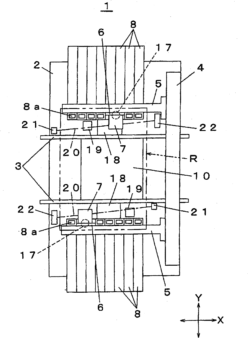
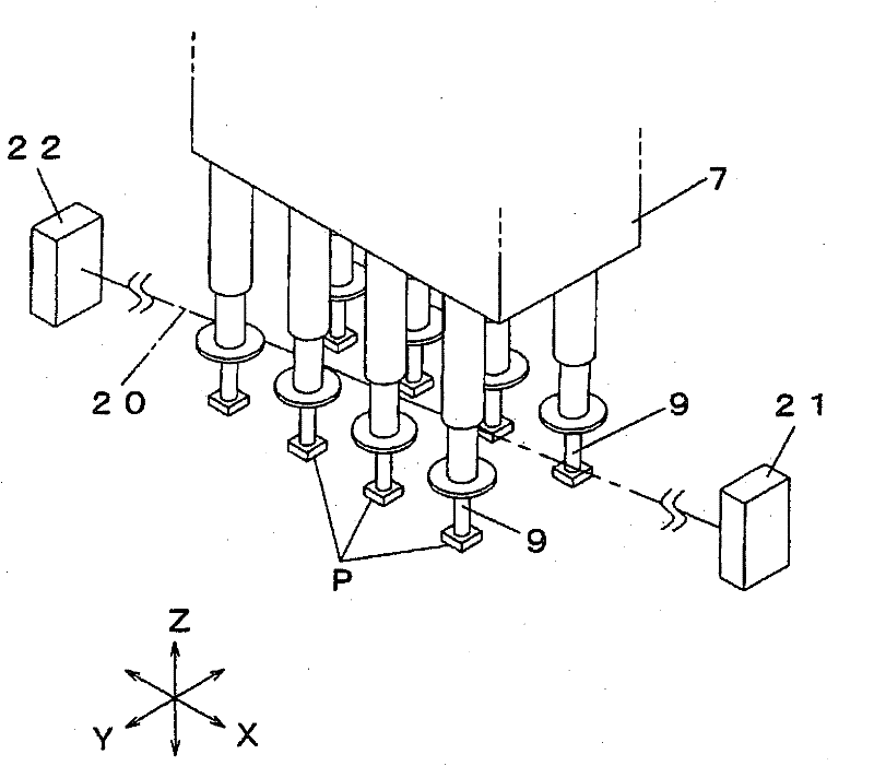
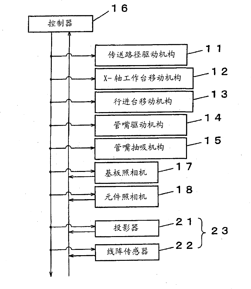
[0031] Embodiments of the present invention will be described with reference to the drawings. figure 1 is a plan view of a component placement apparatus according to an embodiment of the present invention. figure 2 is a perspective view of a mounting head and a line sensor camera according to an embodiment of the present invention. image 3 is a block diagram of a control system of a component placement apparatus according to an embodiment of the present invention. Figure 4 The relationship between the optical axis of the inspection light of the line sensor camera according to the embodiment of the present invention and the traveling track of the mounting head is shown. 5( a ), ( b ), ( c ), ( d ) each show an example of a suction gesture of an element sucked to a suction nozzle according to an embodiment of the present invention. 6( a ), ( b ), ( c ), and ( d ) all show examples of images of components obtained by means of a line array sensor according to an embodiment of...


PUM


Abstract

The invention provides a component placement apparatus capable of preventing free operation of a mounting head within the movable region from being restricted as well as improving the mounting takt time. A component placement apparatus 1 comprising a line sensor camera 23 composed of a projector 21 for projecting inspection light in horizontal direction and a line sensor 22 for receiving the inspection light projected by the projector 21, the component placement apparatus 1 designed to move a mounting head 7 to allow a component P sucked to the suction nozzle 9 of the mounting head 7 before being mounted onto a substrate 10 to horizontally cross the optical axis 20 of the inspection light of the line sensor camera 23 to cause the line sensor camera 23 to perform imaging of the component and to determine the propriety of suction attitude of the component P with respect to the suction nozzle 9 based on the image DP of the component P obtained through imaging of the component P by the line sensor camera 23, characterized in that the projector 21 and the line sensor 22 constituting the line sensor camera 23 are arranged outside the movable region R of the mounting head 7 with respect to the base 2.

Description

technical field [0001] The present invention relates to a component placement apparatus for moving a mounting head relative to a base and mounting components sucked (picked up) by a suction nozzle of the mounting head onto a substrate positioned on the base. Background technique [0002] The component placement apparatus includes a suction nozzle on a mounting head that is movable relative to a base and is designed to suck (pick up) components supplied from a component supply part to the suction nozzle and mount the components to a base plate on the base. Components picked up at the suction nozzle are moved so as to pass over a component camera mounted on a base before being mounted on a substrate, and the component is mounted on a substrate after the component camera performs image recognition (imaging) of the component . From the obtained image information, deviation of the element in a direction around the vertical axis of the suction nozzle (suction deviation) and the ...

Claims


Application Information

Patent Timeline
Patent Type & Authority Patents(China)
IPC IPC(8): H05K13/04
CPCH05K13/0413H05K13/041H05K13/0812Y10T29/49131
Inventor 远藤忠士纳土章永尾和英
Owner PANASONIC CORP
Why Eureka
Try Eureka