
Cutting device of pipe cutting machine tool

A cutting device and machine tool technology, applied in the mechanical field, can solve the problems of low feeding accuracy and efficiency, low cutting accuracy, energy waste, etc., and achieve the effects of good cutting effect, high work efficiency and power saving.

Inactive Publication Date: 2010-06-30
浙江申林智能设备有限公司
View PDF0 Cites 10 Cited by
  • Summary
  • Abstract
  • Description
  • Claims
  • Application Information

AI Technical Summary

Problems solved by technology

At present, the general pipe cutting machine tools on the market are all stationary, and the pipes to be cut are rotated and then cut, which causes a waste of energy during the pipe rotation.
At the same time, the cutting precision of existing pipe cutting machine tools is low, and the precision and efficiency of feeding are low, which ultimately leads to low yield

Method used


Image

  • Cutting device of pipe cutting machine tool
  • Cutting device of pipe cutting machine tool
  • Cutting device of pipe cutting machine tool

Examples


Embodiment Construction

[0022] The following are specific embodiments of the present invention and in conjunction with the accompanying drawings, the technical solutions of the present invention are further described, but the present invention is not limited to these embodiments.

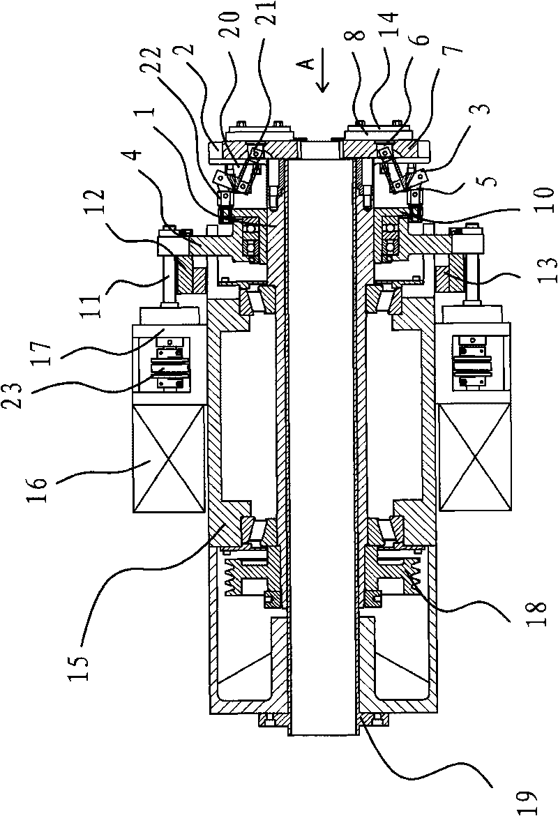
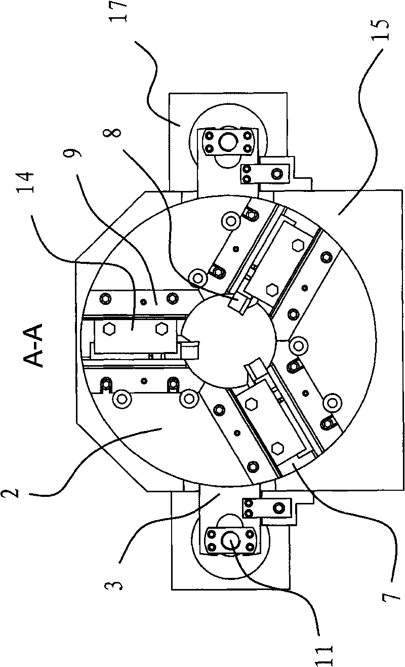
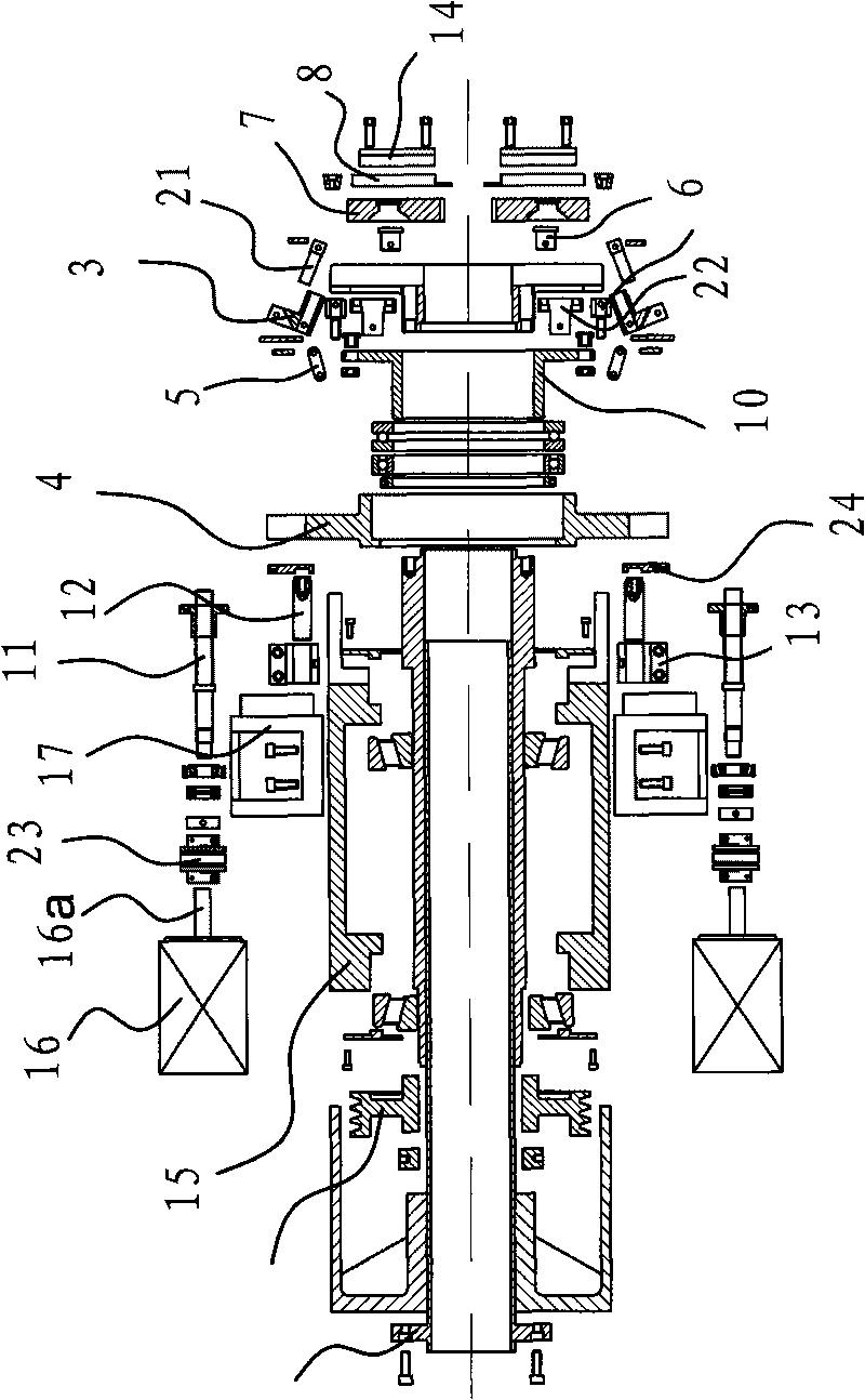
[0023] Such as figure 1 , figure 2 and image 3 As shown, the cutting device of the pipe cutting machine tool is arranged on the machine frame, including a main shaft 1 and a cutter head 2 fixed on the front end of the main shaft 1, and a belt pulley 18 is fixedly connected to the rear end of the main shaft 1, and the main shaft 1 passes through the belt pulley. The belt on the 18 is connected with the main motor, and three sets of cutting elements that are evenly distributed on the outer end face of the cutter head 2 are installed on the cutter head 2 . A headstock 15 is fixedly connected to the frame, the main shaft 1 is located in the headstock 15 and a material guide pipe 19 is inserted on the main shaft 1 . The pi...


PUM


Abstract

The invention provides a cutting device of a pipe cutting machine tool, which belongs to the technical field of machinery. The invention solves the problems of low working efficiency, poor cutting effect, low rate of finished products and the like of the traditional pipe cutting machine tool. The cutting device of the pipe cutting machine tool is arranged on a rack of the machine tool and comprises a main shaft and a cutterhead, wherein the main shaft is connected with a main motor, the cutterhead is fixed on the main shaft, a plurality of sets of cutting elements which are evenly distributed on the outer end face of the cutterhead are installed on the cutterhead, a spindle gearing is fixedly connected on the rack, the main shaft is positioned in the spindle gearing, a motor is fixedly connected on the outer wall of the spindle gearing, a propulsion seat is arranged on the main shaft, a transmission mechanism which can enable the propulsion seat to axially move along the main shaft is arranged between the propulsion seat and the motor, and a feeding mechanism which can enable the cutting elements to radially move along the center of the cutterhead when the propulsion seat moves along the main shaft axially is arranged between the propulsion seat and the cutting elements. The cutting device of the pipe cutting machine tool has the advantages of high working efficiency, good cutting effect and high rate of finished products.

Description

technical field [0001] The invention belongs to the technical field of machinery, and relates to a pipe cutting machine tool, in particular to a cutting device of the pipe cutting machine tool. Background technique [0002] At present, the pipe cutting machine tool is a kind of machine tool equipment commonly used in industrial production, which can cut pipes. The general pipe cutting machine tools in the market are all that the tool is stationary, and the pipe to be cut is rotated and then cut, which causes a part of energy waste in the pipe rotation. At the same time, the cutting precision of the existing pipe cutting machine tools is low, and the precision and efficiency of feeding are low, resulting in a low yield rate. Contents of the invention [0003] The object of the present invention is to provide a cutting device of the pipe cutting machine tool with high working efficiency, good cutting effect, high yield and automatic cutting in view of the above-mentioned pr...

Claims


Application Information

Patent Timeline
Patent Type & Authority Applications(China)
IPC IPC(8): B23D21/00B23Q5/22
Inventor 江方
Owner 浙江申林智能设备有限公司
Learn More