Polymeric barrier removal polishing slurry

A slurry, gravimetric technology, applied in polishing compositions containing abrasives, other chemical processes, chemical instruments and methods, etc., can solve problems such as insufficient barrier removal rate

Inactive Publication Date: 2010-06-30
ROHM & HAAS ELECTRONICS MATERIALS CMP HLDG INC
View PDF6 Cites 12 Cited by
  • Summary
  • Abstract
  • Description
  • Claims
  • Application Information

AI Technical Summary

Problems solved by technology
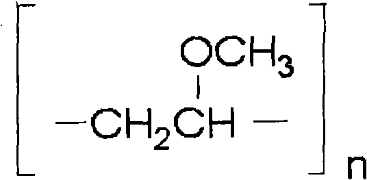
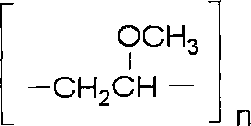
Unfortunately, for some applications the barrier removal rates of these slurries are insufficient

Method used


Image

  • Polymeric barrier removal polishing slurry
  • Polymeric barrier removal polishing slurry
  • Polymeric barrier removal polishing slurry

Examples


Embodiment 1

[0044] Polishing tests used Coral from Novellus Systems, Inc. TM 200 mm wafers of carbon doped oxide (CDO), TEOS dielectric, tantalum nitride and electroplated copper. IC1010 from Rohm and Haas Electronic Materials CMP Technologies (Rohm and Haas Electronic Materials CMP Technologies) was used TM And embossed Politex (Politex) TM The polishing pad polishes the wafer to obtain topographical data.

[0045] Mira (MIRRA) TM A rotary polishing platform polishes the sheet wafer. On decks 1 and 2, use IC1010 TMPolishing pads and Eternal slurry EPL2360 for first step copper polishing. The pad conditioner is a Kinik AD3CG-181060 lattice diamond conditioner disc. The polishing conditions of platform 1 are: the rotation speed of the platen is 93rpm, the rotation speed of the support is 21rpm, and the downward force is 4psi (27.6 kPa). kPa). The polishing conditions of platen 3 are: downward force 1.5psi (10.3kPa), platen speed 93rpm, support speed 87rpm, slurry flow rate 200ml / mi...


PUM

PropertyMeasurementUnit
particle sizeaaaaaaaaaa

Abstract

The aqueous slurry is useful for chemical mechanical polishing semiconductor substrates having copper interconnects. The slurry includes by weight percent, 0 to 25 oxidizing agent, 1 to 50 abrasive particles, 0.001 to 10 inhibitor for decreasing static etch of the copper interconnects, 0.001 to 5 poly (methyl vinyl ether) having a formula as follows: and the poly (methyl vinyl ether) is water soluble and n has a value of at least 5, 0 to 10 copper complexing agent formed during polishing and balance water.

Description

technical field [0001] The present invention relates to an aqueous slurry that can be used to chemically mechanically polish a semiconductor substrate containing copper interconnects and a method for chemically mechanically polishing a semiconductor substrate containing copper interconnects using the aqueous slurry. Background technique [0002] With the development of Ultra Large Scale Integration (ULSI) technology towards smaller line widths, new challenges are presented for the integration of conventional chemical mechanical polishing (CMP) methods. Additionally, the introduction of low-k and ultra-low-k dielectric films requires the use of gentler CMP processes due to the low mechanical strength of these films and their poor adhesion to adjacent layers. In addition, increasingly stringent specifications for defects place additional demands on polishing slurries for low-k films. [0003] Incorporating various low-k films into ULSI may require many additional steps and al...

Claims


Application Information

Patent Timeline
Patent Type & Authority Applications(China)
IPC IPC(8): C09G1/02H01L21/3105
CPCC09G1/02H01L21/3212C09K3/1463C09K3/14H01L21/304
Inventor 卞锦儒叶倩萩
Owner ROHM & HAAS ELECTRONICS MATERIALS CMP HLDG INC
Why Eureka
Try Eureka