
Transmission power control method and system

A technology of transmit power control and transmit power, applied in power management, electrical components, sustainable buildings, etc., and can solve the problems of complicated time-consuming and consumption

Active Publication Date: 2010-06-30
SERCOMM
View PDF1 Cites 10 Cited by
  • Summary
  • Abstract
  • Description
  • Claims
  • Application Information

AI Technical Summary

Problems solved by technology

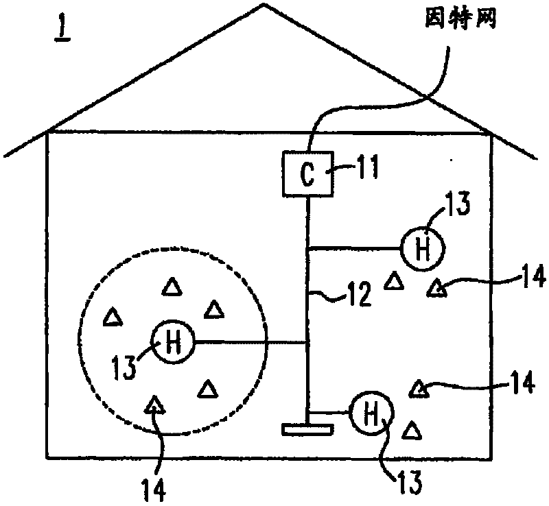
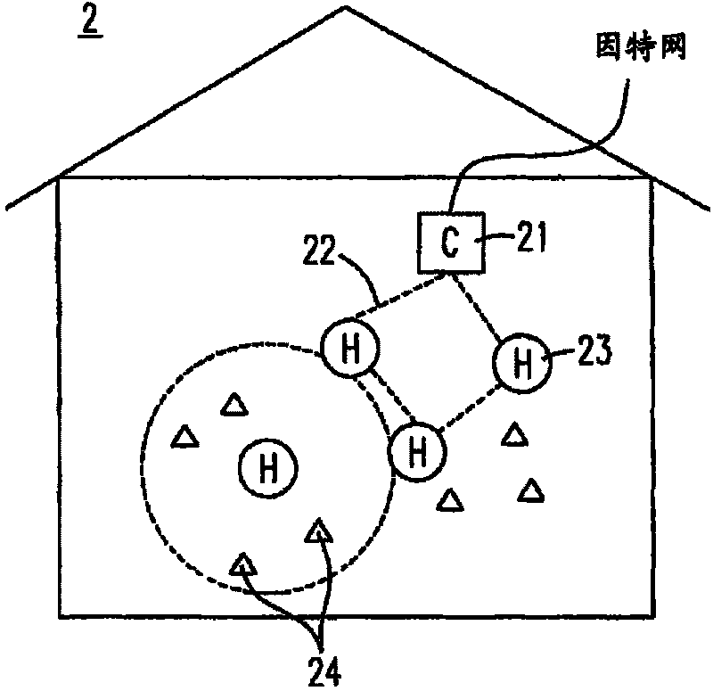
Since the terminal devices 14, 24 often consume a considerable amount of power when detecting the environment and transmitting the data to the back-end cluster heads 13, 23, and for a company or family unit, the number of sensor terminal devices and its replacement The operation of the battery is quite complicated and time-consuming

Method used


Image

  • Transmission power control method and system
  • Transmission power control method and system
  • Transmission power control method and system

Examples


Embodiment Construction

[0051] The technical means of the present invention will be described in detail as follows. It is believed that the purpose, characteristics and characteristics of the present invention can be understood in depth and specifically. However, the following examples and illustrations are only provided for reference and illustration, and are not used to explain the present invention. limit.

[0052] See first image 3 , which is a schematic flowchart of the first embodiment of the transmission power control method of the present invention, and please also refer to Figure 4 , which is a schematic diagram of the sensor network layout of the first embodiment of the transmission power control method of the present invention, in Figure 4 Among them, the cluster head 43 is the cluster head of the three terminal devices 441, 442, and 443, which have three transmission power levels, L1, L2, and L3 from low to high. First, according to image 3 In the process shown, the cluster head 43...


PUM


Abstract

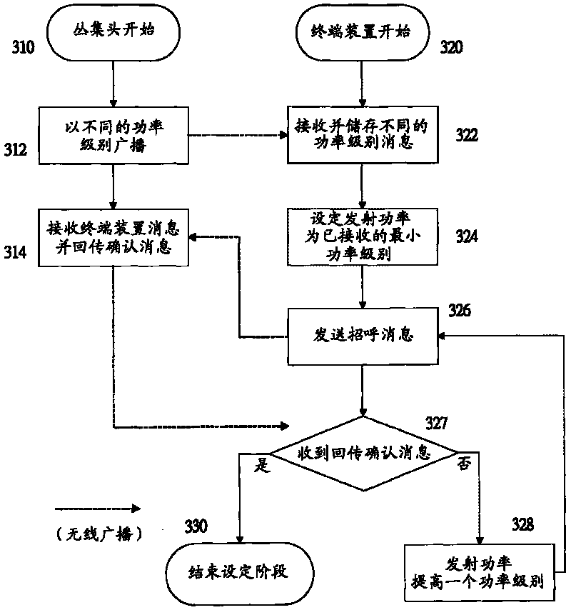
The invention aims at providing a transmission power control method and a system, so as to utilize the transmission power control of a terminal device to reduce the electric energy consumption of the terminal device and further prolong the service life of the terminal device. The transmission power control method comprises the following steps: (A) using a plurality of mutually different transmission power to broadcast respective power level messages; and (B) setting the transmission power of the terminal device as the minimum value of the power level messages received by the terminal device.

Description

technical field [0001] The present invention relates to a transmission power control method and system, in particular to a method and system for controlling transmission power of a wireless network terminal device. Background technique [0002] With the advancement of MEMS technology and the development of wireless transmission technology, the application of wireless sensor networks (WirelessSensor Networks) has become more and more popular. The wireless sensor network is a network system composed of one to several wireless data collectors and a large number of sensors (Sensor), and the communication method between components is wireless communication, so sensors can be placed arbitrarily or The wireless data collector is extremely convenient and fast in arrangement. Under the framework of the wireless sensing network, the design of the sensor is aimed at power saving, low price, small size, and sensing environment devices, which can target the things we are interested in i...

Claims


Application Information

Patent Timeline
Patent Type & Authority Applications(China)
IPC IPC(8): H04W52/26H04W24/04H04W68/00
CPCY02B60/50
Inventor 李俊贤庄俊杰
Owner SERCOMM
Learn More