
Handle-frame-type rolling pole

A rolling pin and stand-type technology, applied in the field of rolling pins, can solve the problems of cumbersome operation and inconvenience, and achieve the effect of strong applicability and widening of the plane working range

Inactive Publication Date: 2011-10-26
宁波市鄞州千峰机械科技有限公司
View PDF5 Cites 0 Cited by
  • Summary
  • Abstract
  • Description
  • Claims
  • Application Information

AI Technical Summary

Problems solved by technology

[0002] When using the existing single rolling pin to roll the dough, in order to make the dough be evenly pressed in all directions, it is necessary to continuously lift the rolling pin, change the direction and continue rolling the dough. This operation is very cumbersome
At the same time, when the traditional rolling pin is working, it relies on rolling the rolling pin in the palm of the hand to move the rolling pin, which determines that the one-time maximum continuous working range of the rolling pin will not exceed the size of the palm of a person. When rolling a large area of ​​dough, it is necessary to It is very inconvenient to adjust the position of the rolling pin several times

Method used


Image

  • Handle-frame-type rolling pole
  • Handle-frame-type rolling pole
  • Handle-frame-type rolling pole

Examples


Embodiment Construction

[0011] The present invention will be further described below in conjunction with the accompanying drawings and embodiments.

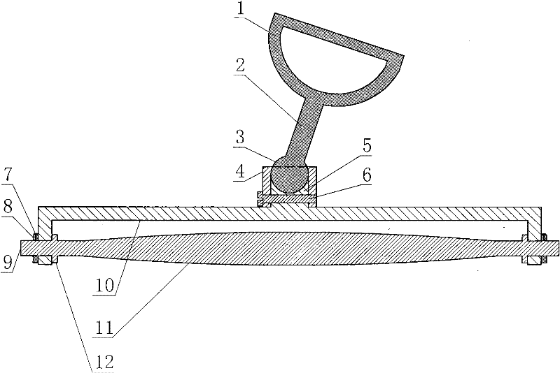
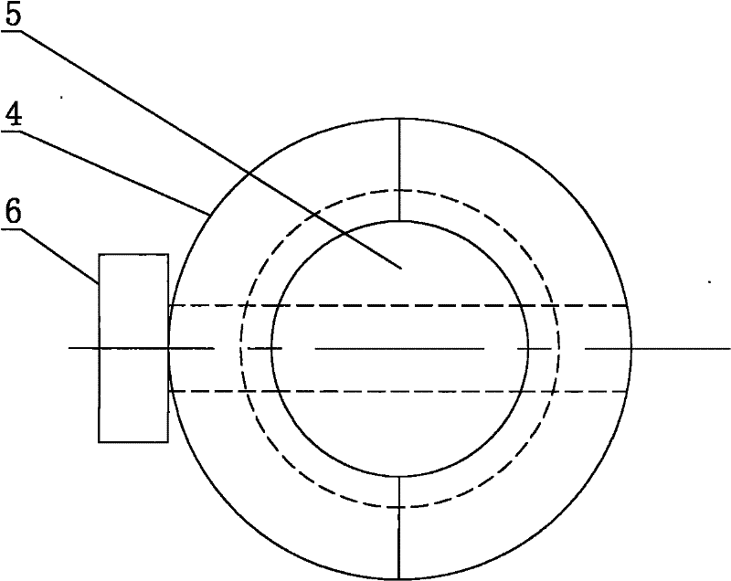
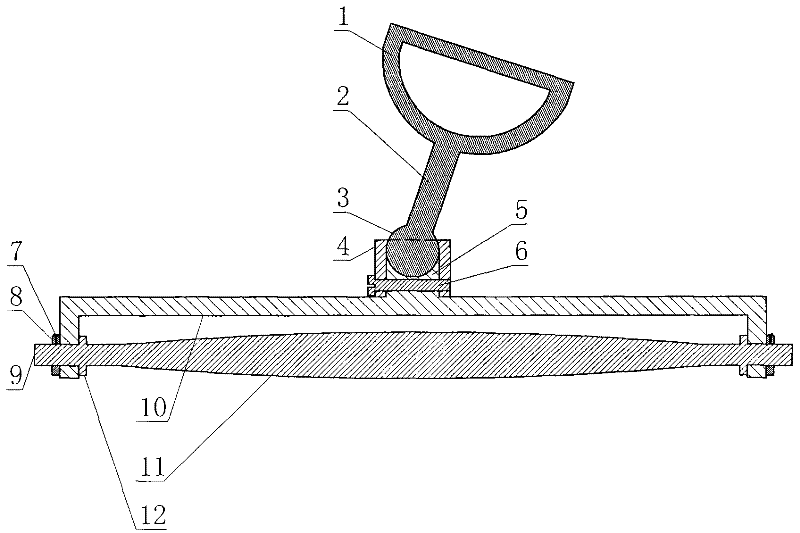
[0012] The handle rack type rolling pin consists of a handle 1, a handle 2, a handle ball 3, a clamping ball tube 4, a concave column 5, a tie screw 6, a locking screw 7, a nut 8, a stick handle 9, a fixed frame 10, a stick body 11 and a clamp Ring 12 constitutes. The handle 1 is a D-shaped ring body, and the middle part of the arc segment of the handle 1 is welded with a cylindrical handle 2. The other end of the handle 2 is a handle ball 3 integral with the handle 2. The handle 3 is a hemispherical concave cylinder with the same radian, and the diameter of the concave column 5 is the same as that of the handle 3 . The lower half of handle 3 is in the concavity of concave post 5 upper ends, and card ball tube 4 is made of two half cylinders, and the upper end inner side of each half cylinder has the arc surface identical with handle 3 radians. The in...


PUM


Abstract

The invention relates to a rolling pole, in particular to a handle-frame-type rolling pole which comprises a grip, a handle, a handle ball, a ball-clamping cylinder, a concave column, a lacing screw, a locking screw, a screw cap, a pole handle, a fixing frame, a pole body and a snap ring. The handle ball is arranged at the other end of the handle and integrated with the handle; the lower half part of the handle ball is arranged in the concave at the upper end of the concave column; the ball-clamping cylinder is sleeved on the concave column; and the handle ball is limited in a space formed byan arc surface at the inner side of the upper end of the ball-clamping cylinder and a semi-spherical concave at the upper end of the concave column and can rotate in the space. The pole body of the rolling pole can continuously and freely turn on the surface of dough along with the force-applying direction of the hand of a person, and a cook can roll the dough evenly by conveniently adjusting therolling direction of the pole body. Meanwhile, the rolling pole has greatly widened plane working range and stronger suitability.

Description

technical field [0001] The invention relates to a rolling pin, in particular to a handle frame type rolling pin. Background technique [0002] When using the existing single rolling pin to roll the dough, in order to make the dough be pressed evenly in all directions, it is necessary to constantly lift the rolling pin, change the direction and continue rolling the dough. Such an operation is very cumbersome. At the same time, when the traditional rolling pin is working, it relies on rolling the rolling pin in the palm of the hand to move the rolling pin, which determines that the one-time maximum continuous working range of the rolling pin will not exceed the size of the palm of a person. When rolling a large area of ​​dough, it is necessary to It is very inconvenient to adjust the position of the rolling pin several times. Contents of the invention [0003] In order to solve the deficiencies of the prior art, the present invention provides a handle frame type rolling pin...

Claims


Application Information

Patent Timeline
Patent Type & Authority Patents(China)
IPC IPC(8): A21C3/02
Inventor 佘玲
Owner 宁波市鄞州千峰机械科技有限公司
Learn More