
Transmission for bicycle

A transmission device and bicycle technology, which is applied to wheel transmission devices, chain/belt transmission devices, vehicle components, etc., and can solve problems such as difficult application of pedals

Inactive Publication Date: 2010-07-07
MAVIC SA
View PDF9 Cites 3 Cited by
  • Summary
  • Abstract
  • Description
  • Claims
  • Application Information

AI Technical Summary

Problems solved by technology

[0017]Finally, since it is impossible to obtain a transmission ratio close to 1, a foot with a planetary gear Pedals are hard to apply

Method used


Image

  • Transmission for bicycle
  • Transmission for bicycle
  • Transmission for bicycle

Examples


Embodiment approach

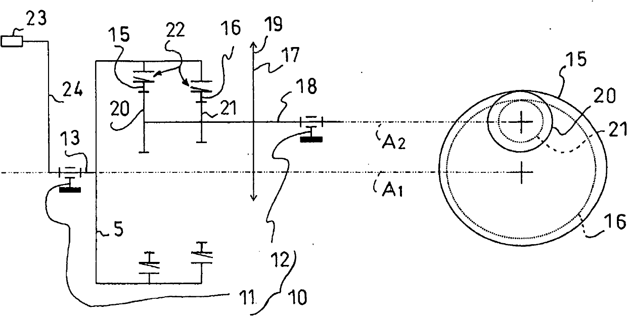
[0165] The clutchable locking part 22 is arranged to alternately lock the rotation of the first toothed element 15 relative to the pedal 5, while the second toothed element 16 remains free to rotate, or lock the second toothed element 16 The first toothed element now remains free to rotate with respect to the rotation of the pedal. As with the first embodiment, it is also entirely possible to lock the rotation of one toothed element relative to the wheel and the other toothed element relative to the pedal 5 .

[0166] Figure 17 A perspective view (left 3 / 4) of the first sub-assembly consisting of the "pedal cover" 10 and the pedal 5 is shown. The casing 10 includes a main body 11 and a secondary body 12 . The main body 11 corresponds to a conventional pedal cover. This involves a cylindrical sleeve which is inserted into a correspondingly shaped opening provided in the vehicle frame 2 . The secondary body 12 is arranged in an extension of the main body, on the right side ...


PUM


Abstract

A transmission device for a cycle, such as a bicycle, which includes a bottom bracket fixed relative to the remainder of the cycle frame. The device includes a cylindrical main body centered about a first axis and a secondary body centered about a second axis, the second axis being parallel to, but not merged with, the first axis; a crankset rotationally mounted along the first axis relative to the main body and including a pair of cranks, a first circular toothed element and a second circular toothed element, both being centered on the first axis; a chainwheel rotationally mounted along the second axis relative to the secondary body and including a third circular toothed element and a fourth circular toothed element, both being centered on the second axis; the first and third toothed elements and the second and fourth toothed elements constituting a first gear train and a second gear train, respectively; a disengageable blocking device provided to block, selectively, the rotation of the first toothed element relative to the crankset or the rotation of the third toothed element relative to the chainwheel, on the one hand, and the rotation of the second toothed element relative to the crankset or the rotation of the fourth toothed element relative to the chainwheel, on the other hand.

Description

technical field [0001] This invention relates to transmissions for bicycles. In particular, the invention relates to variable speed transmissions. [0002] In a bicycle, the mechanical component that transmits the force of the rider's pedaling to the drive wheels as a whole is called the transmission. Background technique [0003] The transmission may comprise gear shifting components, or more precisely, gear ratio changing components. Such components have been used since the invention of the early two- or three-wheeled bicycles with pedals in the second half of the 19th century. The overall transmission ratio, which will hereafter be referred to as the transmission gear ratio, corresponds to the rotational speed ratio between the "input", or pedaling speed, and the "output", or driving wheel speed. In bicycles where the pedaling axis does not coincide with the drive wheel axis, the transmission ratio change can be effected either at the pedals, or at the drive wheel, or ...

Claims


Application Information

Patent Timeline
Patent Type & Authority Applications(China)
IPC IPC(8): B62M9/1242B62M9/1246B62M1/24
CPCB62M11/04
Inventor J-P·梅卡B·克勒图
Owner MAVIC SA
Features
  • Generate Ideas
  • Intellectual Property
  • Life Sciences
  • Materials
  • Tech Scout
  • Unparalleled Data Quality
  • Higher Quality Content
  • 60% Fewer Hallucinations
Learn More