Detailed design for working drawing of bent-torsional member
What is AI technical title?
AI technical title is built by Patsnap AI team. It summarizes the technical point description of the patent document.
A technology for detailed design of bending and torsion components, applied in the field of detailed design of construction drawings, can solve problems such as complex detailed design, achieve the effect of guiding workshop production and avoiding mistakes
Active Publication Date: 2012-11-21
潮峰钢构集团有限公司
View PDF0 Cites 0 Cited by
Summary
Abstract
Description
Claims
Application Information
AI Technical Summary
This helps you quickly interpret patents by identifying the three key elements:
Problems solved by technology
Method used
Benefits of technology
Problems solved by technology
The exterior of these new steel structures is unique, and the surface is mostly streamlined. Such a shape will inevitably lead to a very complicated detailed design
Method used
Image
Click on the blue label to locate the original text in one second.
Reading with bidirectional positioning of images and text.
Examples
Embodiment 1
[0022] Embodiment 1: refer to Figure 1-9 . The detailed design method of the construction drawing of the bending and torsion member includes the following steps:
[0023] a. In the computer, according to the coordinates of the outer contour given by the construction drawing of the bending and torsion member, they are connected with spline curves to form a space line network;
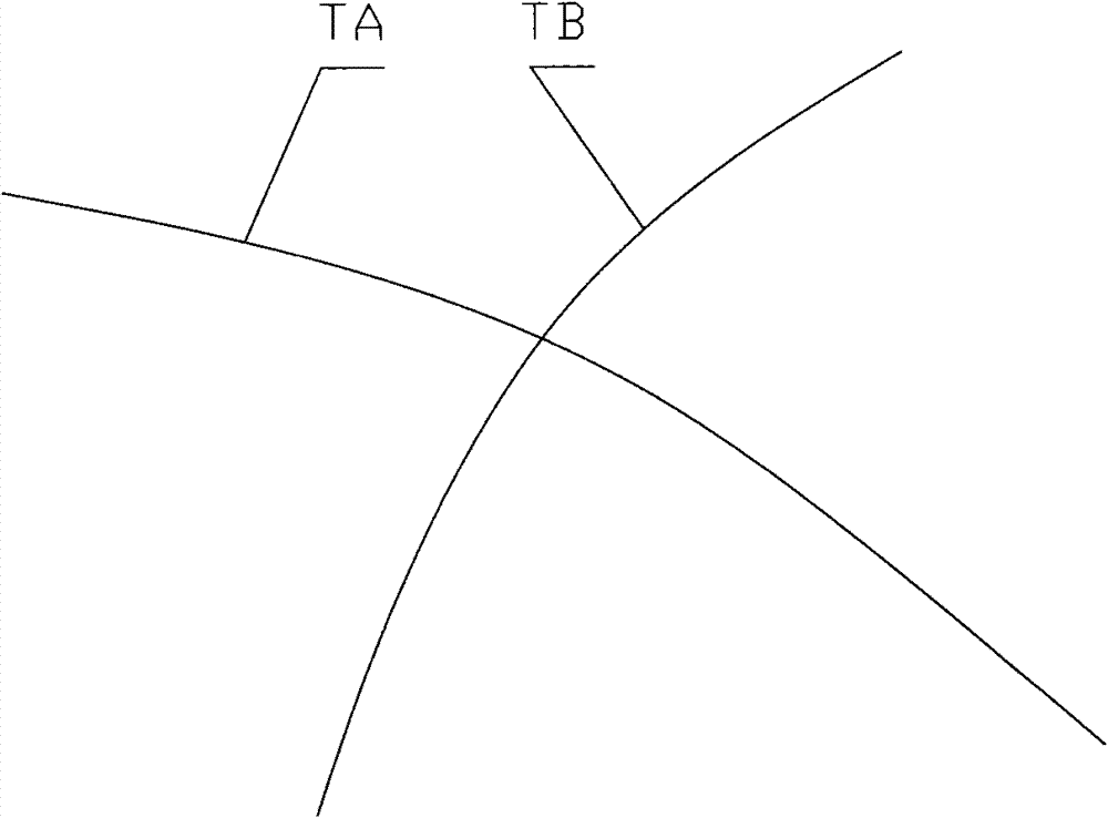
[0024] b. Select two intersecting spline curves TA and TB with larger curvature in the space line network;
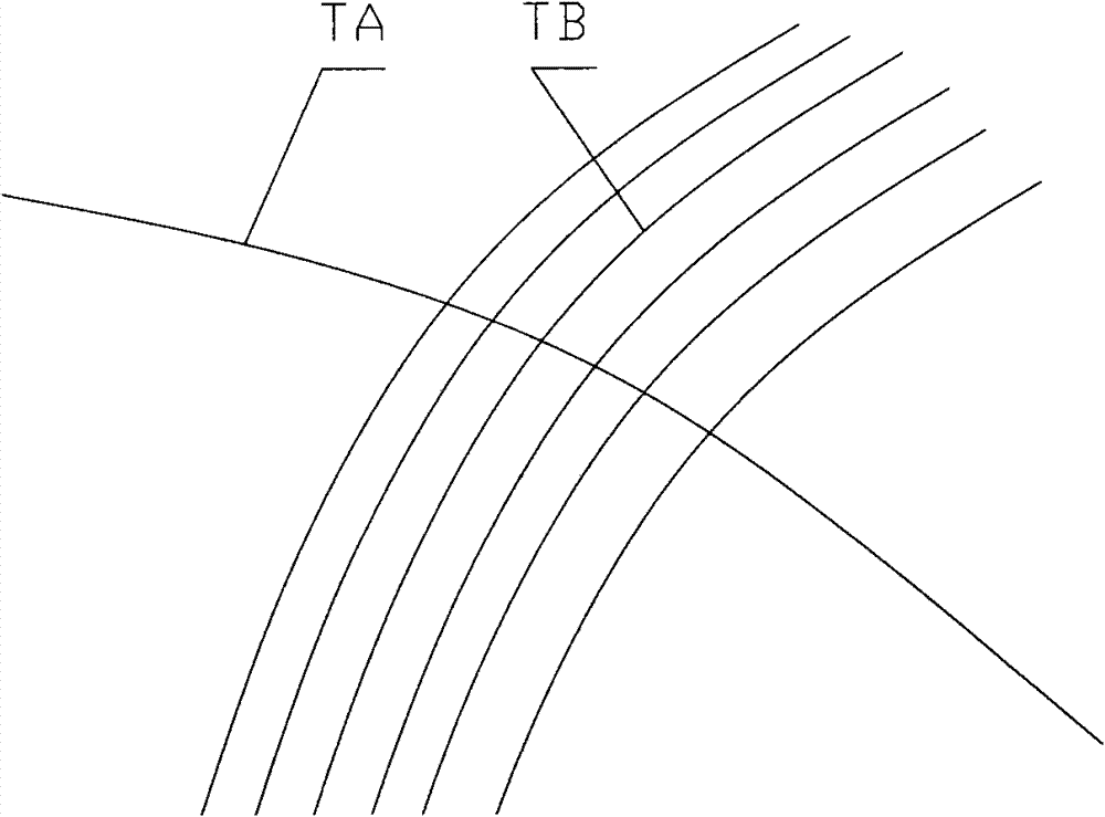
[0025] c. According to the offset x given in the construction drawing of the bending and torsion member, the two spline curves are respectively offset into four curves, and the connecting line between the four curves is formed into a rectangle;
[0026] d. For the four curves offset by two intersecting spline curves, every two adjacent curves form a surface. Select the surface generated by the four curves offset by one of the spline curves as a whole, and use the other curve The surface genera...
Embodiment 2
[0030] Embodiment 2: refer to figure 1 and 2 . The two intersecting spline curves described in step b are two spline curves with relatively large curvature in the space line network.
Embodiment 3
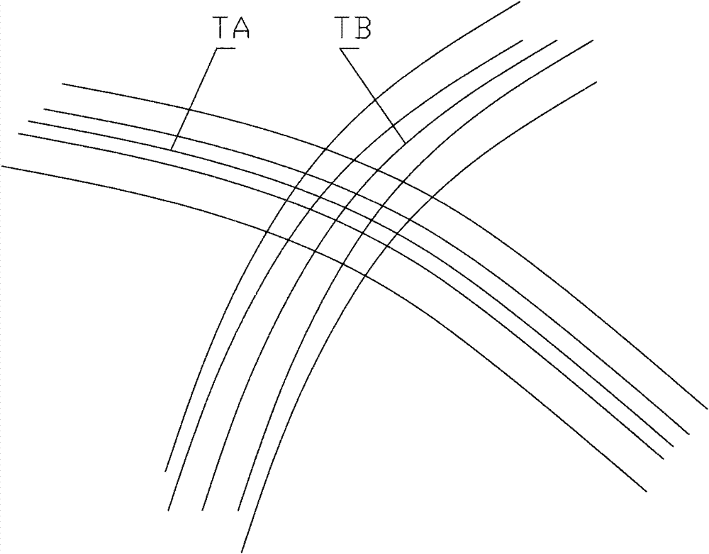
[0031] Embodiment 3: refer to image 3 , 4 , 5, 6, 7 and 8. In step d, the spline curve TA offsets four curves according to the given offset x of the construction drawing of the bending and torsion member, which are curves TA1, TA2, TA3 and TA4, and the adjacent two curves TA1 and TA2 form a surface V1, and the curve TA2 and TA3 form a surface V2, curves TA3 and TA4 form a surface V3, and curves TA4 and TA1 form a surface V4;
[0032] Select the surface composed of the four offset curves from TA as a whole, then the spline curve TB is cut into two parts, namely TB1, TB2, and TB3, according to the given offset x of the construction drawing of the bending and torsion member. . Curves TB6 and TB7 form surface V5, curves TB6 and TB7 form surface V6, curves TB7 and TB8 form surface V7, and curves TB8 and TB5 form surface V8; each surface is stretched by y distance to form a plate, where y is the construction drawing of the bending and torsion member A given stretch distance.
PUM
Abstract
The invention relates to a detailed design for a work drawing, in particular to a detailed design for a working drawing of a bent-torsional member, which comprises the following steps of: a, connecting spline curves according to coordinates of the outline of the bent-torsional member to form a space net; b, selecting two spline curves with intersecting curvatures in the space net; c, deviating four curves from the two intersecting spline curves respectively; d, forming a curved surface by every two adjacent curves and stretching the formed surface inwards for a distance of y to form a plate; e, drawing a plurality of groups of triangles on the plate surface of each plate respectively, wherein the vertexes of the triangles are all positioned on the curves deviated from the spline curves and the triangles in the plate surfaces of two adjacent plates share the vertexes of intersected curves of the two plates; f, drawing a coordinate position table of each vertex according to the vertex positions of each triangle on the plate surface of the plate; and g, obtaining a plate sample drawing for blanking and processing. The detailed design has the advantages of effectively controlling simulation errors, avoiding making members wrongly, making the produced members be closer to the requirement of theoretical design and effectively guiding workshop production.
Description
technical field [0001] The invention relates to a detailed design of construction drawings, in particular to a method for detailed design of construction drawings of bending and torsion components. Background technique [0002] In recent years, domestic space steel structures have developed greatly, especially some large-span bending-torsion steel structures (or combined steel structures) have developed very rapidly. The exterior of these new steel structures is unique, and the surface is mostly streamlined. Such a shape will inevitably lead to a very complicated detailed design. Contents of the invention [0003] The object of the present invention is to provide a construction drawing deepening design method for bending and torsion members in order to avoid the deficiencies in the background technology. [0004] In order to achieve the above object, the present invention adopts the following technical scheme: the construction drawing deepening design method of the bendin...
Claims
Application Information
Patent Timeline
Application Date:The date an application was filed.
Publication Date:The date a patent or application was officially published.
First Publication Date:The earliest publication date of a patent with the same application number.
Issue Date:Publication date of the patent grant document.
PCT Entry Date:The Entry date of PCT National Phase.
Estimated Expiry Date:The statutory expiry date of a patent right according to the Patent Law, and it is the longest term of protection that the patent right can achieve without the termination of the patent right due to other reasons(Term extension factor has been taken into account ).
Invalid Date:Actual expiry date is based on effective date or publication date of legal transaction data of invalid patent.

