Method, system and device for allocating uplink reference signals
A reference signal and configuration method technology, applied in the field of communication, can solve problems such as the inability to guarantee the orthogonality of uplink reference signals of different UEs
- Summary
- Abstract
- Description
- Claims
- Application Information
AI Technical Summary
Problems solved by technology
Method used
Image
Examples
Embodiment 1
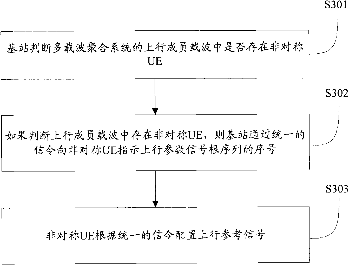
[0058] Such as image 3 As shown, it is a flowchart of the configuration method of the uplink reference signal in Embodiment 1 of the present invention. In this embodiment, the signaling sent by the base station to all asymmetric UEs on the same uplink component carrier is the same, that is, unified signaling. The length of the signaling may refer to the length of the current Cell ID, preferably 9 bits. Specifically include the following steps:
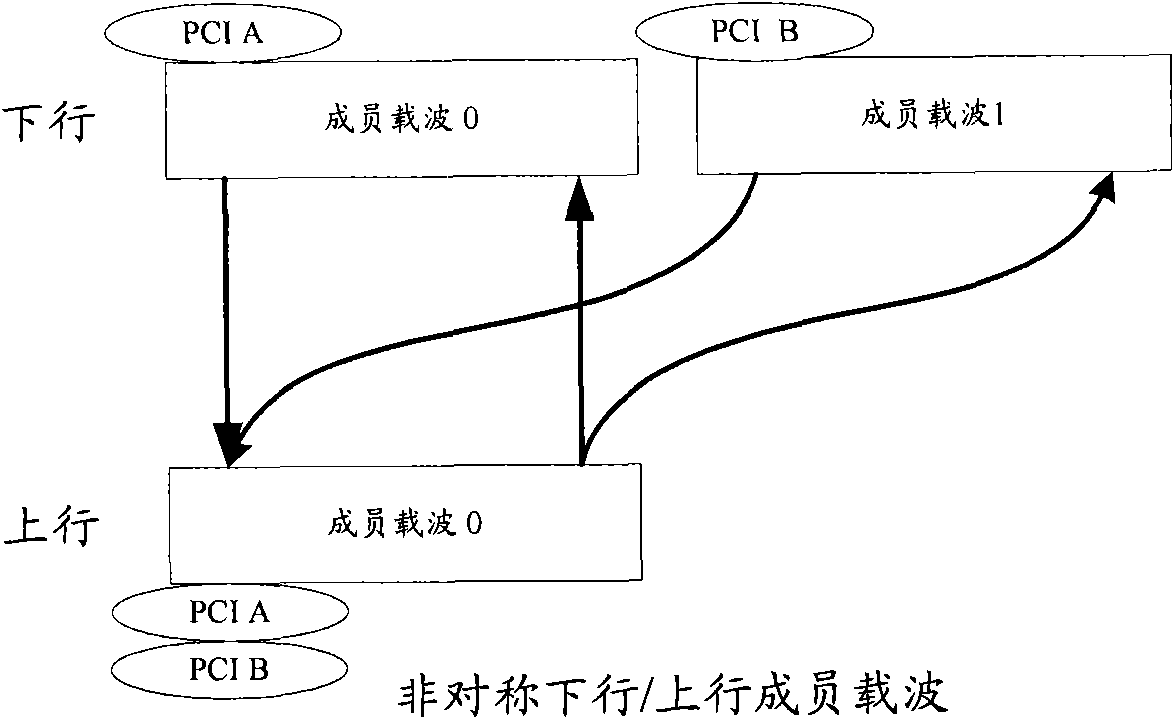
[0059] In step S301, the base station judges whether there is an asymmetric UE in the uplink component carrier of the multi-carrier aggregation system, where the asymmetric UE refers to a UE that occupies the same uplink component carrier and different downlink component carriers.
[0060] Step S302, if it is judged that there is an asymmetric UE in the uplink component carrier, the base station sends a unified signaling Indicates the sequence number of the root sequence of the uplink parameter signal to the asymmetric UE. The uni...
Embodiment 2
[0070] Such as Figure 4 As shown, it is a flow chart of the configuration method of the uplink reference signal in Embodiment 2 of the present invention. In this embodiment, the base station sends signaling to asymmetric UEs on the same uplink component carrier respectively. The signaling It is related to the cell ID corresponding to the asymmetric UE, and the signaling corresponding to each asymmetric UE and the sum of the cell ID are equal, so as to ensure that the UE can use the uplink reference signal root sequence in the same group. The length of the signaling is preferably 5 bits. Specifically include the following steps:
[0071] Step S401, the base station judges whether there is an asymmetric UE in the uplink component carrier of the multi-carrier aggregation system, where the asymmetric UE refers to the UE that occupies the same uplink component carrier and different downlink component carriers.
[0072] Step S402, if it is judged that there is an asymmetric...
Embodiment 3
[0081] If the Cell IDs of all downlink component carriers are broadcast in the broadcast information, the base station can directly select one of the Cell IDs as the Cell ID used by the asymmetric UE when determining the uplink reference signal sequence, and send the selected Cell ID to The UE is notified that this embodiment can also ensure the orthogonality between the uplink reference signal sequences.
[0082] Such as Figure 5 As shown, it is a structural diagram of an uplink reference signal configuration system according to an embodiment of the present invention, including a base station 100 and at least one UE 200 served by the base station 100 . The base station 100 is used to judge whether there is an asymmetric UE in the uplink component carrier of the multi-carrier aggregation system. The asymmetric UE is a UE that occupies the same uplink component carrier and occupies a different downlink component carrier. When it is judged that there is an asymmetric UE, by Th...
PUM
 Abstract
Description
Claims
Application Information
 - R&D
- Intellectual Property
- Life Sciences
- Materials
- Tech Scout
- Unparalleled Data Quality
- Higher Quality Content
- 60% Fewer Hallucinations
Browse by: Latest US Patents, China's latest patents, Technical Efficacy Thesaurus, Application Domain, Technology Topic, Popular Technical Reports.
© 2025 PatSnap. All rights reserved.Legal|Privacy policy|Modern Slavery Act Transparency Statement|Sitemap|About US| Contact US: help@patsnap.com


