
Limited volume high performance flush valve assembly

A technology of flushing valves and components, applied in flushing equipment with water tanks, water supply devices, buildings, etc., to achieve high fluid flow rate and more available energy

Active Publication Date: 2010-07-07
IDEAL STANDARD INT
View PDF3 Cites 2 Cited by
  • Summary
  • Abstract
  • Description
  • Claims
  • Application Information

AI Technical Summary

Problems solved by technology

[0007] While applicant's prior art solution effectively removes excreta from the toilet within government guidelines, such guidelines no longer require a minimum "depression time"

Method used


Image

  • Limited volume high performance flush valve assembly
  • Limited volume high performance flush valve assembly
  • Limited volume high performance flush valve assembly

Examples


Embodiment Construction

[0024] Detailed description of the preferred embodiment

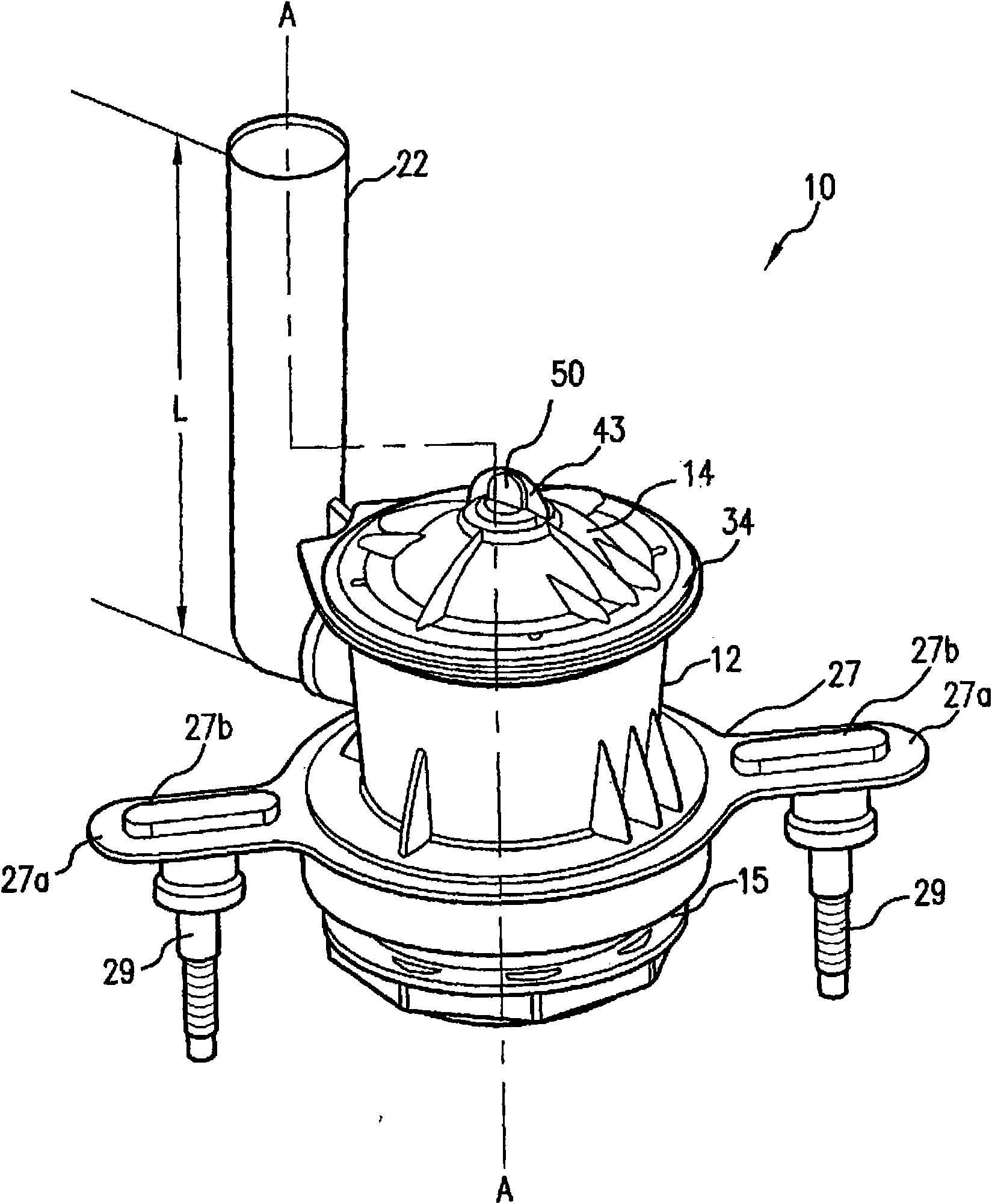
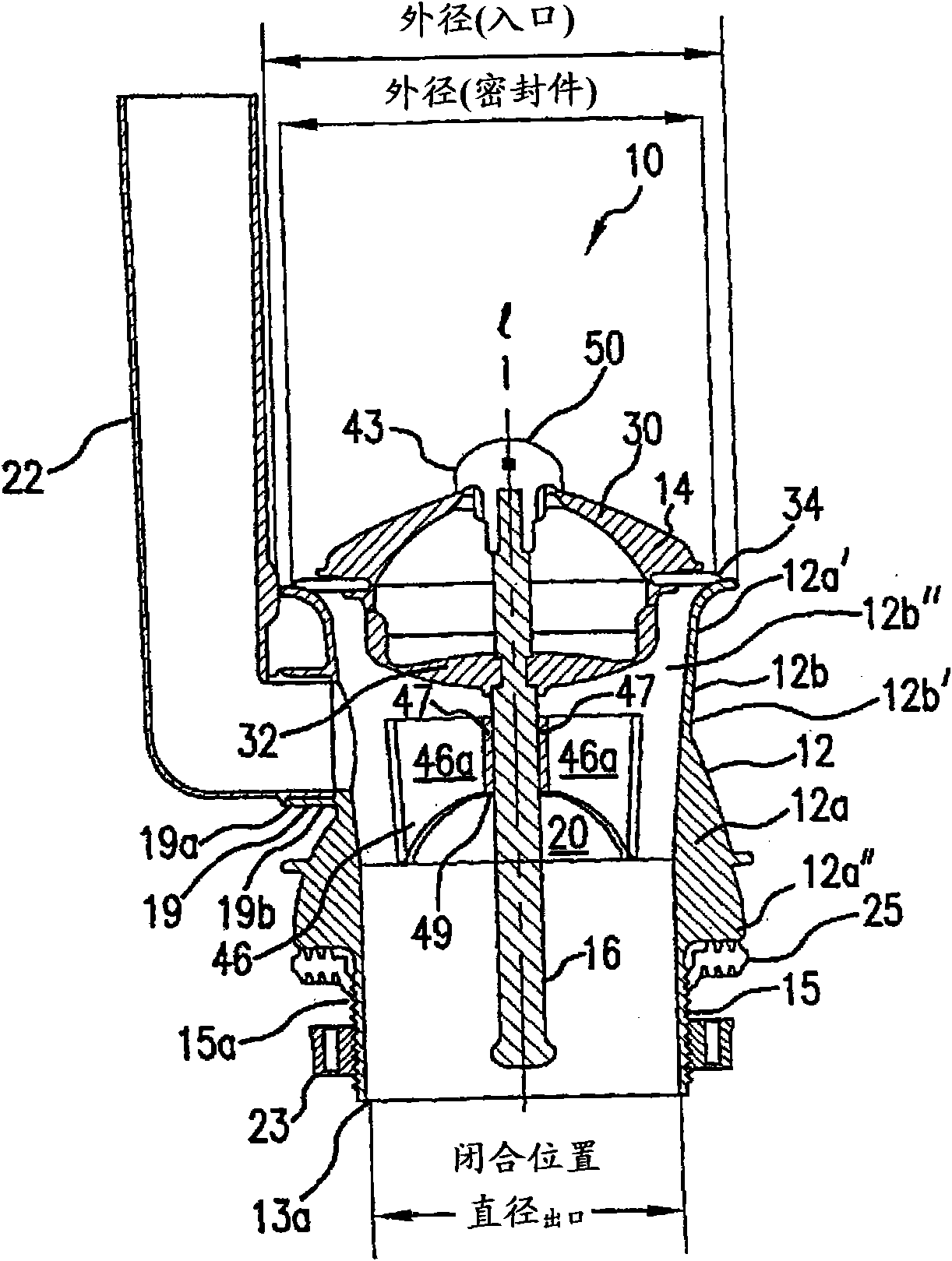
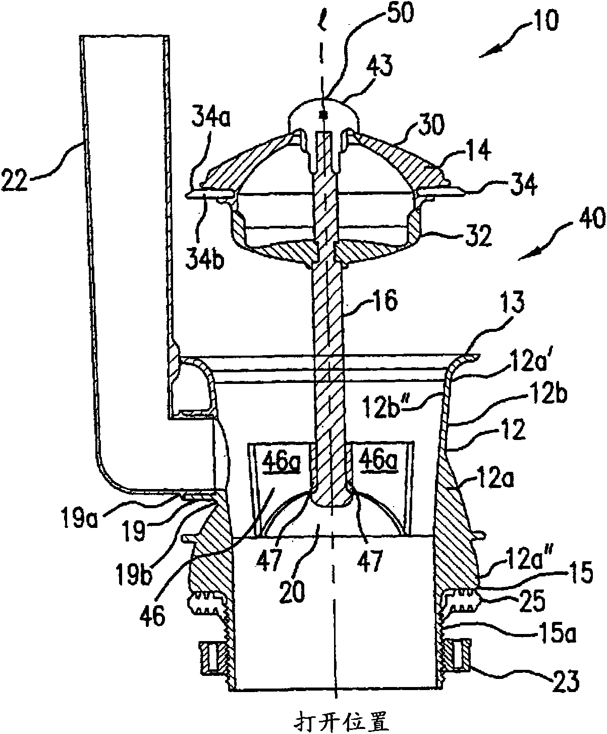
[0025] As shown, wherein like numerals indicate like elements, the flush valve assembly 10 of the present invention is disposed in a tank 200 of a toilet assembly (in Figure 4 shown in ), wherein the water tank stores water for delivery to a bowl in fluid communication with the water tank. Flush valve assembly 10 is operable with a conventional priming valve 205, which may be selected from any known priming valve consistent with the successful practice of the present invention. Flush valve assembly 10 is operable upon actuation of an actuating device, such as trip lever 210, as further described below.

[0026] Valve assembly 10 includes a body subassembly 12 in operative communication with a movable poppet sealing subassembly 14 via a guide rod 16 having a predetermined length. The main body subassembly 12 includes a valve body 12a having a proximal extension 12a' and a distal extension 12a" and a coextensive wall 1...


PUM


Abstract

A flush valve assembly of the present invention includes a body subassembly in operable communication with a movable poppet seal subassembly via a guide rod of a predetermined length. The body subassembly inlet is substantially located above the tank floor, thereby reducing available tank discharge volume. The poppet subassembly includes a float having upper and lower float covers with an annularseal disposed therebetween. The poppet subassembly remains coaxially and slidably mounted with respect to the body subassembly so as to create a valve opening therebetween when the poppet subassemblyis removed from its initial closed position to a second open position. Guide structure in the body subassembly accommodates reciprocatable movement of the guide rod and inhibits deviation of the guide rod from a predetermined axial guide path when the poppet subassembly is in use during a flush cycle. An optional valve bracket may be provided.

Description

[0001] This application claims the benefit of the filing date of US Patent Serial No. 60 / 842,203, filed August 31, 2006, the disclosure of which is incorporated herein by reference in its entirety. field of invention [0002] The present invention relates to a flush valve assembly for use in a water closet tank. More specifically, the present invention relates to flushometer assemblies having enhanced energy production provided by a single moving part. The valve assembly of the present invention provides a complete, unobstructed flow path (thus maximizing energy production), but also includes structures that limit tank discharge to less than 2 gallons. So constructed, the present invention ensures compliance with applicable water protection regulations without compromising flushing performance. Background of the invention [0003] Water closets for removal of excreta are well known. Typically, toilets incorporate three systems that work together to perform the flushing act...

Claims


Application Information

Patent Timeline
Patent Type & Authority Applications(China)
IPC IPC(8): E03D1/35
CPCE03D1/304E03D1/35
Inventor R·M·詹森
Owner IDEAL STANDARD INT
Learn More