
Retractable hot runner system

A hot runner and telescopic technology, applied in the field of hot runner, can solve the problems of reducing the temperature of the hot runner, heat loss of the hot runner system, and high matching accuracy between the hot runner system and the mold, and achieve the effect of reducing processing requirements and reducing heat loss.

Inactive Publication Date: 2010-07-14
深圳市米高科技有限公司
View PDF3 Cites 2 Cited by
  • Summary
  • Abstract
  • Description
  • Claims
  • Application Information

AI Technical Summary

Problems solved by technology

[0003] The existing hot runner system is to assemble the hot nozzle with the fixed mold plate, and press it tightly through the hot runner plate and the fixed mold seat plate, so as to ensure that the hot runner will not leak glue during the entire injection molding process, which will affect its normal use.
The hot runner system mainly has the following deficiencies: 1. The molds that need to be matched with it require high processing precision, especially for larger molds. If the mold cavity is slightly deviated, it will affect the assembly and use of the entire hot runner system.
2. When the hot runner system cooperates with the mold, multiple contact points are required to increase the contact area between the hot runner system and the mold, thereby reducing the heat loss on the hot runner system and reducing the temperature of the hot runner
3. The length and position of the existing hot nozzle tip are usually fixed. When the length of the hot nozzle tip deviates slightly, it is basically impossible to adjust. Therefore, the matching precision of the hot runner system and the mold is high, which requires increased processing difficulty
4. Inconvenient installation and maintenance

Method used


Image

  • Retractable hot runner system
  • Retractable hot runner system
  • Retractable hot runner system

Examples


Embodiment Construction

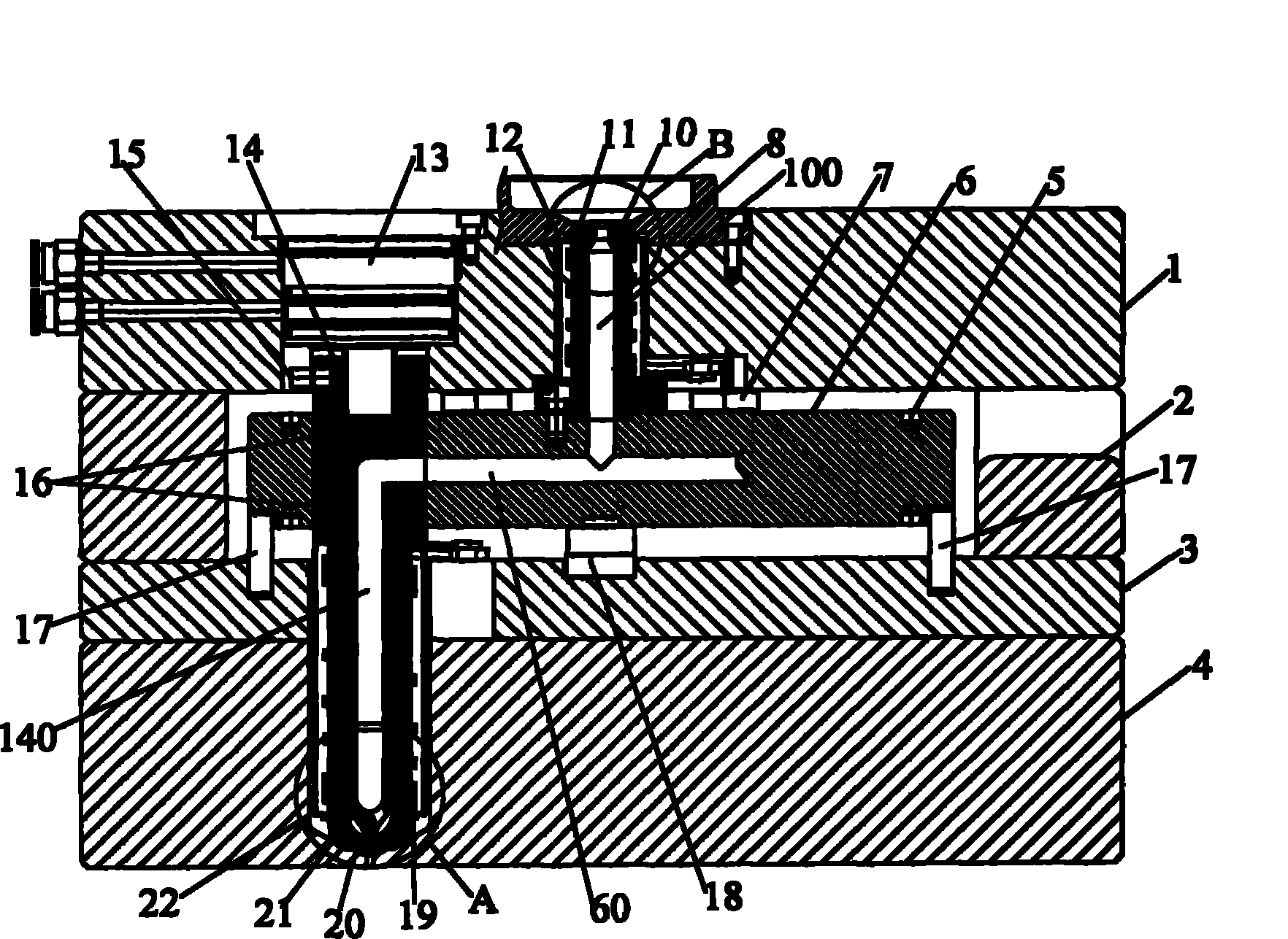
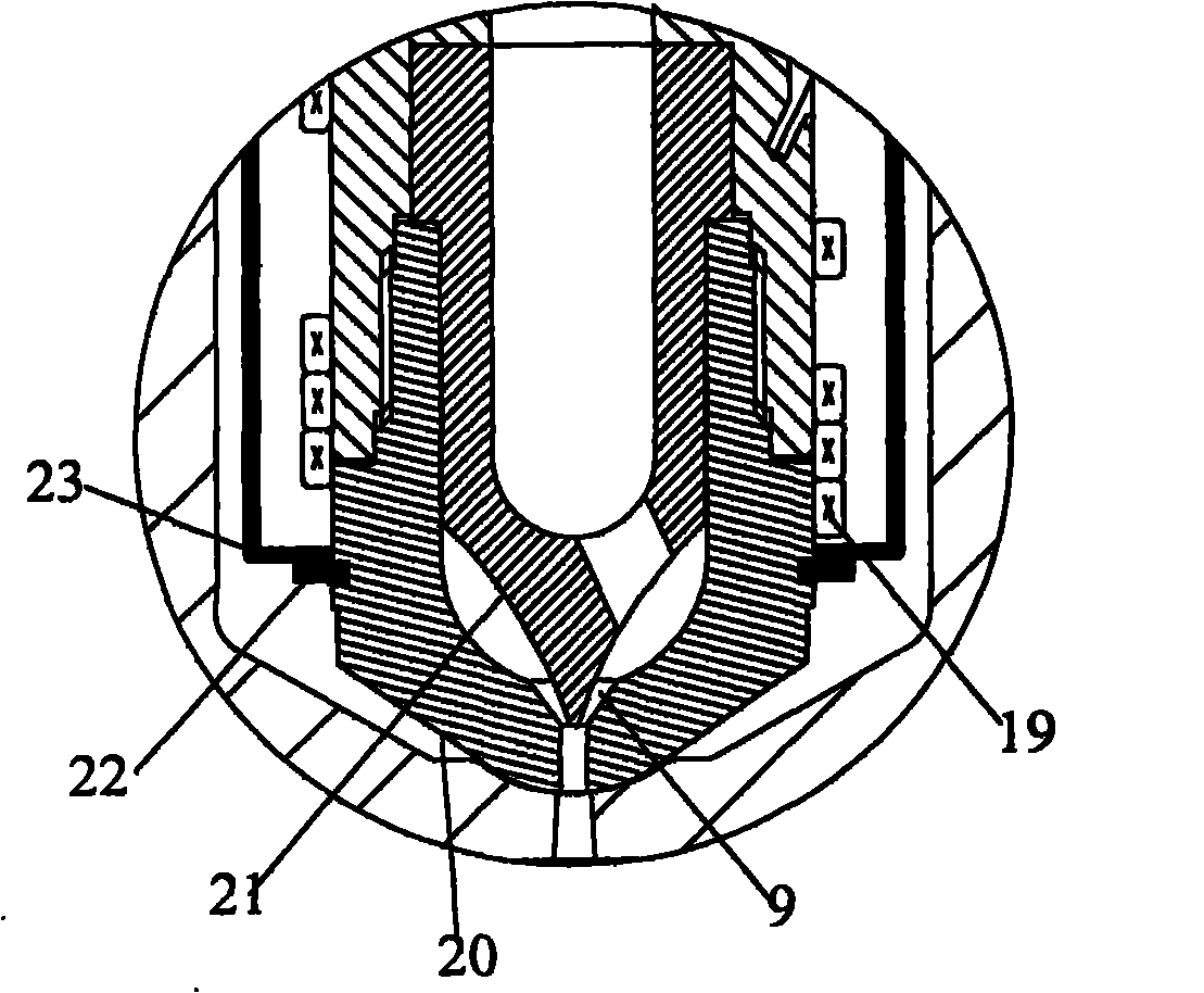
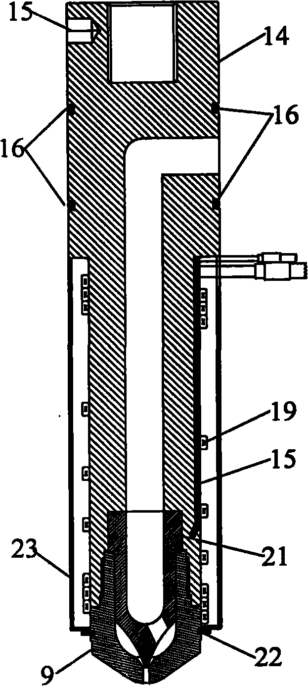
[0024] Such as figure 1 , figure 2 and image 3 As shown, the present invention provides an embodiment of a telescopic hot runner system.

[0025] The telescopic hot runner system includes: a hot nozzle body 14, a hot runner plate 6, a main nozzle 10 and a driving device 13 connected to the hot nozzle body 14, wherein the hot runner hole on the hot nozzle body 14 140 communicates with one end of the hole 60 on the hot runner plate 6, and the other end of the hole 60 communicates with the through hole 100 on the main nozzle 10; the nozzle body 14 is provided with a first heating ring 19, a nozzle tip 21 and a heater Nozzle gate department 20, the hot nozzle gate department 20 is fixed with the hot nozzle tip 21 and the hot nozzle body 14; the hot runner plate 6 is provided with a heat pipe 5, and a There is a support ring 18 ; the second heating ring 11 is wound around the outside of the main nozzle 10 .

[0026] Specifically, the driving device 13 includes a pneumatic dev...


PUM


Abstract

The invention discloses a retractable hot runner system. The system comprises a hot nozzle main body, a hot runner plate, a main nozzle and a driving device which is connected with the hot nozzle main body, wherein the hot nozzle main body is fixedly connected with the driving device, a hot runner hole on the hot nozzle main body is communicated with one end of a hole on the hot runner plate and the other end of the hole is communicated with a through hole on the main nozzle; the hot nozzle main body is provided with a first heating ring, a hot nozzle point and a hot nozzle gate bush and the hot nozzle gate bush is matched and fixed with the hot nozzle point and the hot nozzle main body; the hot runner plate is provided with a heating pipe and a support ring is arranged between the hot runner plate and a padding plate; and a second heating ring is wound outside the main nozzle. Compared with the prior art, the retractable hot runner system has the advantages that: the gate bush is only required to be matched with a die in position, so the die is simpler and the assembly and use of the whole hot runner system are not affected even if the processing precision on a die cavity is a little inaccurate; and meanwhile, the periphery of the gate bush contacts the die cavity exclusively, so thermal loss can be reduced.

Description

technical field [0001] The invention relates to the technical field of hot runners, in particular to a telescopic hot runner system. Background technique [0002] Hot runner technology is an advanced technology for thermoplastic injection molding. Its principle is to heat the gating system of the mold to keep the plastic melt in the molten state in the runner, so as to avoid the condensation of the gating system during the molding cycle. That is, the nozzle material, so that the melt remaining in the hot runner system can be injected into the cavity during the next injection. [0003] The existing hot runner system is to assemble the hot nozzle with the fixed mold plate, and press it tightly through the hot runner plate and the fixed mold seat plate, so as to ensure that the hot runner will not leak glue during the entire injection molding process, which will affect its normal use. . The hot runner system mainly has the following deficiencies: 1. The molds that need to be ...

Claims


Application Information

Patent Timeline
IPC IPC(8): B29C45/20B29C45/74
Inventor 高成鹏孙文华
Owner 深圳市米高科技有限公司
Learn More