Oil tank and gas tank fire control cooling valve

A technology of cooling valve and gas tank, which is applied to tank trucks, valve details, valve devices, etc., can solve the problems of untimely cooling, blind watering, and difficulty in cooling, and achieve the effect of improving water flow and realizing interchangeability.

Inactive Publication Date: 2010-07-14
黄益怀
View PDF0 Cites 11 Cited by
  • Summary
  • Abstract
  • Description
  • Claims
  • Application Information

AI Technical Summary

Problems solved by technology

The obvious defect of this method is that it is difficult for operators to grasp the temperature rise and temperature field of oil tanks and gas tanks, so it is also difficult to implement cooling more accurately, resulting in serious consequences if the cooling is not timely. Either blindly watering, resulting in a great waste of water quality

Method used


Image

  • Oil tank and gas tank fire control cooling valve
  • Oil tank and gas tank fire control cooling valve

Examples


Embodiment Construction

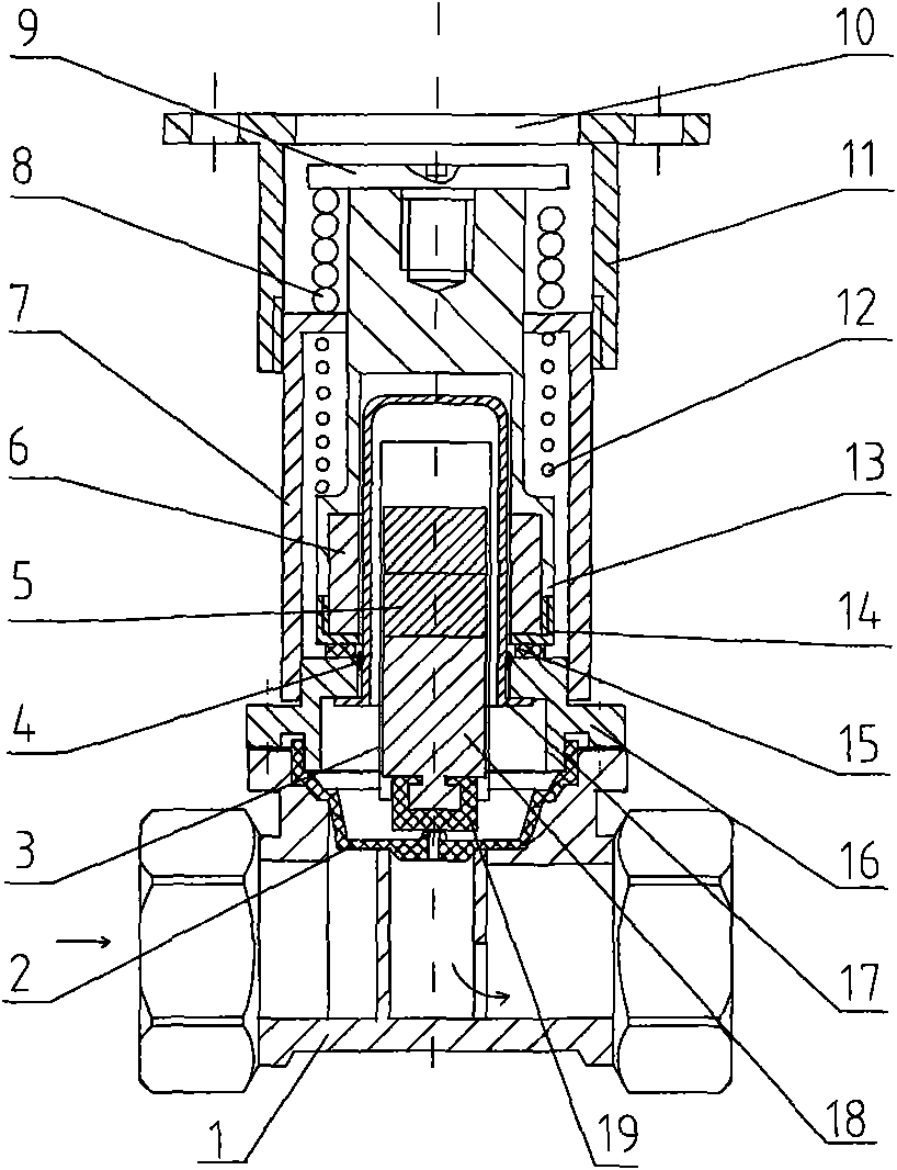
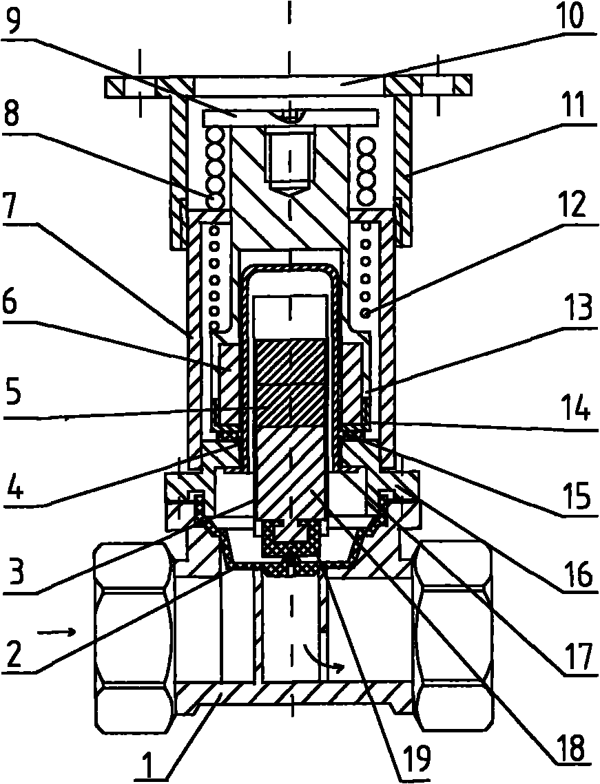
[0007] Accompanying drawing is the principle structural diagram of present embodiment. The invention consists of a valve body (1) and a temperature control head. There is a cylindrical water outlet in the valve body (1). A piston (2) is installed on the upper end of the water outlet. The pressure relief hole on the piston (2) cooperates with the piston rod (19) at the bottom of the valve core (3). (2) and a small through hole communicates with the water inlet of the valve body (1); the piston column (19) passes through the packing pad (17), and presses the magnetic column (5) into the valve core sleeve (16) to form the valve core (3); the upper end of the valve body (1) is connected together with the bonnet (16) by bolts, and the center hole in the bonnet (16) is equipped with a spool sleeve (17), and is welded (see welding point (4) )) is connected with the spool cover (17); the spool (3) is inserted in the spool cover (17), and can move up and down in the spool cover; the o...


PUM


Abstract

The invention relates to an oil tank and a gas tank fire control cooling valve which belong to the field of cooling fire control automatic control equipment, and are characterized in that a cylindrical water outlet is arranged in the valve body; the upper end of the water outlet is provided with a diaphragm piston; through a filled pad, a piston column presses a magnetic cylinder in a valve core sleeve to form a valve core; the outer surface of the valve core sleeve is sleeved with a magnetic ring sleeve; in the magnetic ring sleeve, an upper magnetic ring cover and a lower magnetic ring cover install a magnetic ring component in the magnetic ring sleeve by thread; and the magnetic ring sleeve can slide in the valve core sleeve up and down. The invention can be automatically opened or closed according to the changes to the surface temperature of the oil tank and the gas tank, and achieves the purpose of cooling the oil tank and the gas tank.

Description

technical field [0001] The utility model relates to a fire-fighting cooling valve for oil tanks and gas tanks, which belongs to the field of cooling and fire-fighting automatic control equipment. Background technique [0002] When the ambient temperature of the existing large-scale oil storage tanks and gas storage tanks is getting higher and higher, for example, in summer, the outer surface temperature of the oil tanks and gas tanks is as high as 60, 70 degrees, or even higher, which greatly affects the safety of production. danger. Oil and gas stations have to manually use high-pressure water to cool down the oil tanks and gas tanks when such high temperatures occur. The obvious defect of this method is that it is difficult for operators to grasp the temperature rise and temperature field of oil tanks and gas tanks, so it is also difficult to implement cooling more accurately, resulting in serious consequences if the cooling is not timely. Either blindly watering, result...

Claims


Application Information

Patent Timeline
Patent Type & Authority Applications(China)
IPC IPC(8): F16K31/64B65D88/74
Inventor 全龙浩钟茂干
Owner 黄益怀
Why Eureka
Try Eureka