Flat-plate loop heat pipe

A loop heat pipe, flat-plate technology, applied in the field of flat-plate loop heat pipe, can solve the problem of small steam flow resistance

Inactive Publication Date: 2010-07-14
金积德
View PDF0 Cites 10 Cited by
  • Summary
  • Abstract
  • Description
  • Claims
  • Application Information

AI Technical Summary

Problems solved by technology

[0004] In view of this, aiming at the shortcomings of the above-mentioned existing devices, the main purpose of the present invention is to provide a flat-plate loop heat pipe, which can also allow the formed vapor to escape to the evaporation chamber unde

Method used


Image

  • Flat-plate loop heat pipe
  • Flat-plate loop heat pipe
  • Flat-plate loop heat pipe

Examples


Embodiment Construction

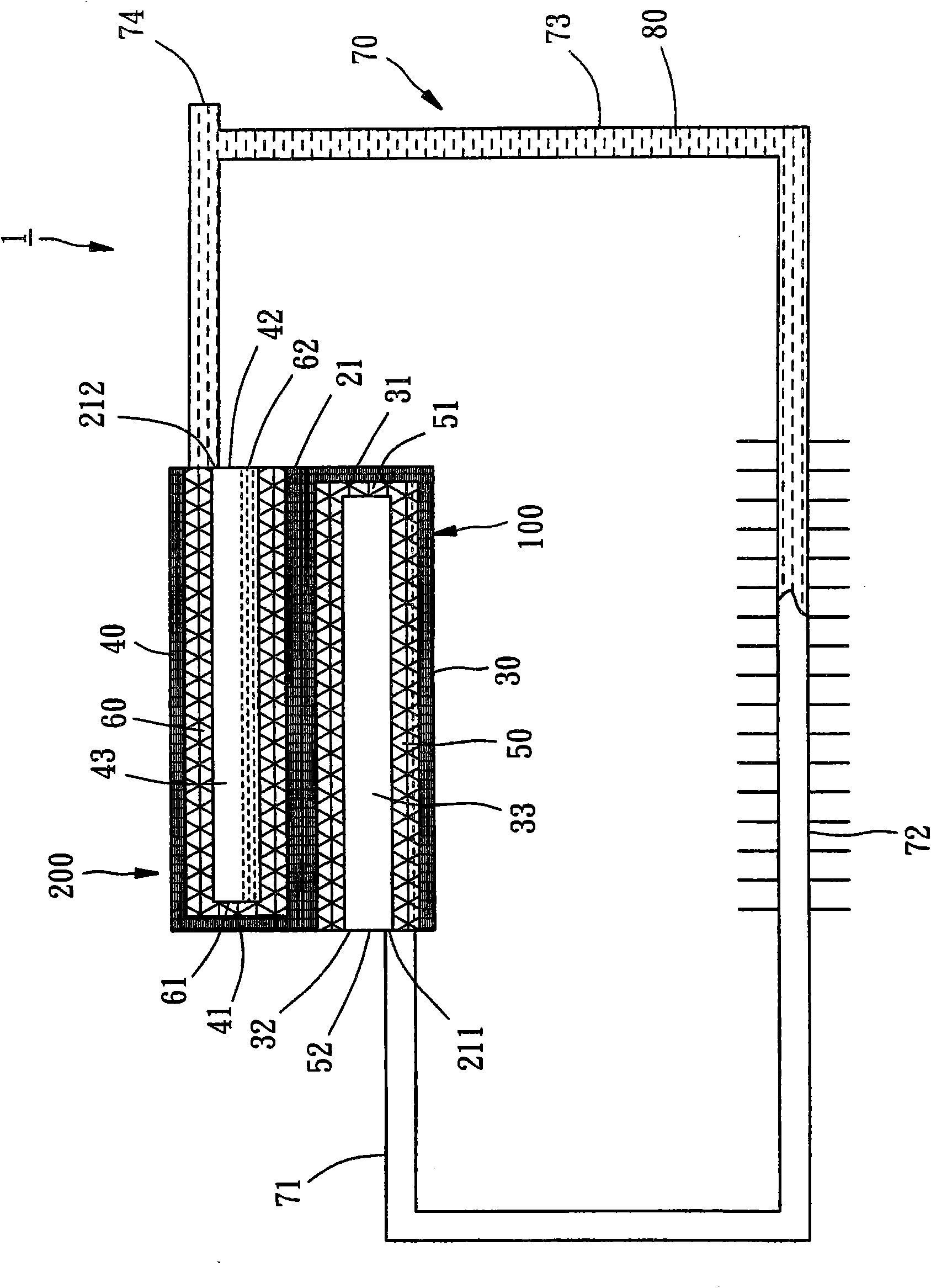
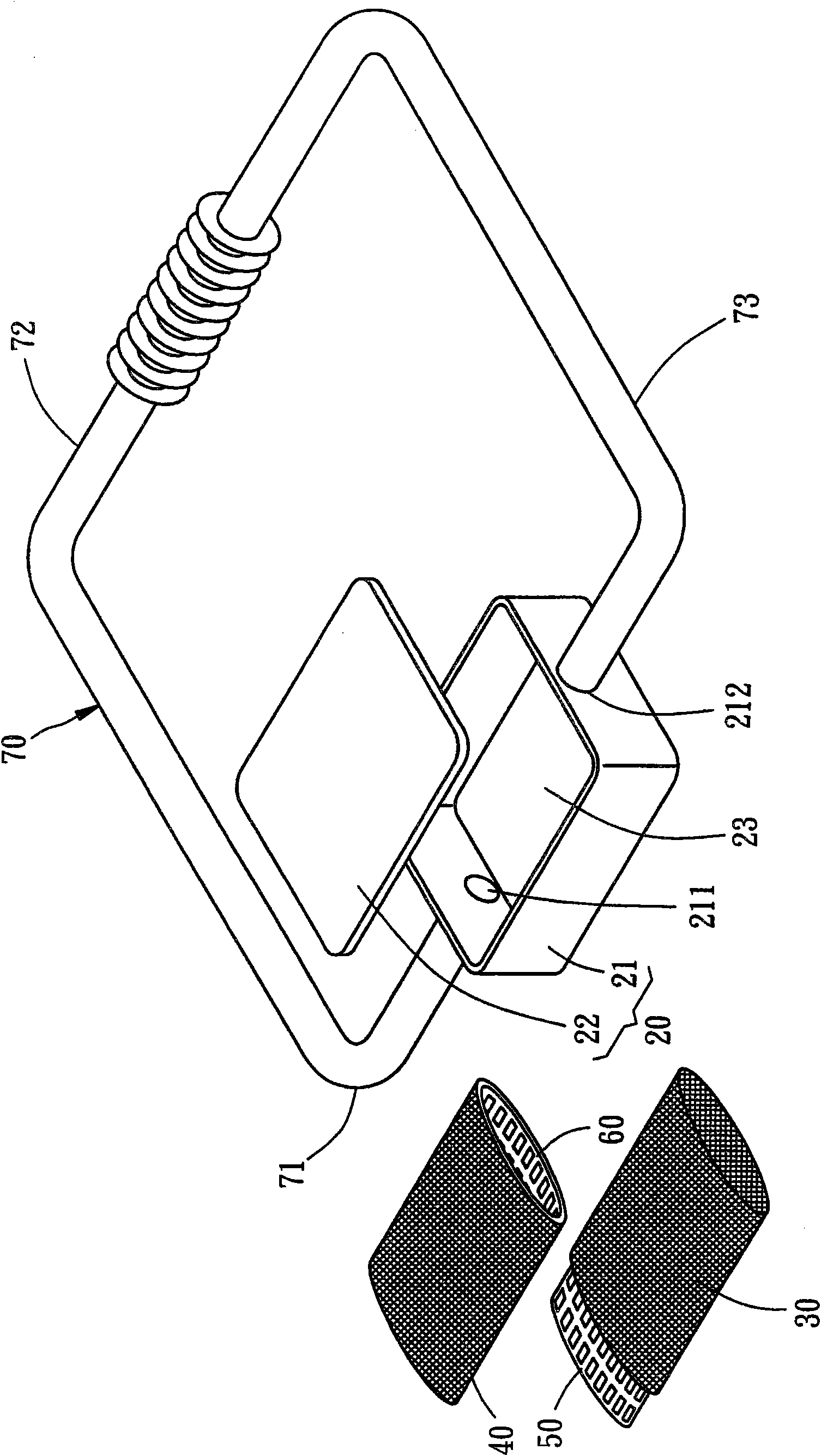
[0013] see Figure 1 to Figure 4 , the flat-plate loop heat pipe 1 of a preferred embodiment of the present invention includes: a container 20 , two liquid-absorbing cores 30 , 40 , two support frames 50 , 60 , a circulation pipe 70 and a working fluid 80 .

[0014] The container 20 includes a box body 21 and a cover body 22, which are combined to form a chamber 23; the box body 21 has two openings, which are respectively a steam outlet 211 and a liquid inlet 212; the steam outlet 211 The distance between the central position of the steam outlet 211 and the bottom of the box body 21 is smaller than the distance between the central position of the liquid inlet 212 and the bottom of the box body 21 , and the steam outlet 211 and the liquid inlet 212 are respectively located on the left and right sides of the box body 21 .

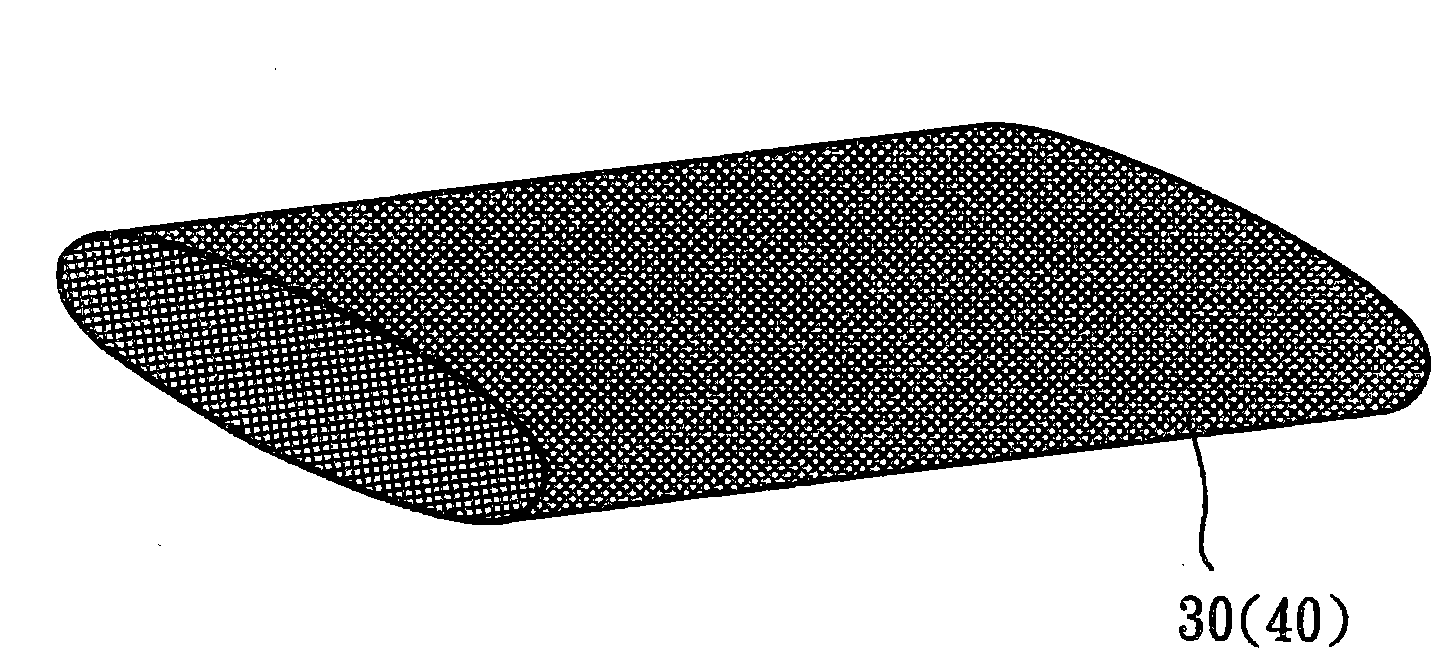
[0015] The liquid-absorbent cores 30, 40 have a capillary structure, and are respectively a first liquid-absorbent core 30 and a second liquid-absorbent core...


PUM


Abstract

The invention discloses a flat-plate loop heat pipe. A first liquid aspirating core and a first supporting frame form an evaporation chamber; and a second liquid aspirating core and a second supporting frame form a compensated chamber. Therefore, the problems that the conventional loop heat pipe is difficult to start under low-wattage heat sources and the first liquid aspirating core is dried up are solved.

Description

technical field [0001] The present invention is related to the heat fransfer element, and more specifically refers to a flat-plate loop heat pipe. Background technique [0002] A loop heat pipe (LHP) is an effective heat dissipation element; a general loop heat pipe includes an evaporator, a vapor line, a condenser and a liquid line. line), and the above components communicate with each other to form a circuit; the circuit is still filled with working fluid, and the evaporation part has a capillary structure connected to a heat source; a compensation chamber is provided between the liquid pipeline and the capillary structure in the evaporation part (compensation chamber). When the evaporation part of the loop heat pipe absorbs the heat from the heat source, the working fluid in the loop heat pipe also absorbs the heat from the heat source and evaporates to form steam; the steam flows through the steam pipeline through the condensation part, and releases heat and condenses i...

Claims


Application Information

Patent Timeline
IPC IPC(8): F28D15/02
Inventor 金积德
Owner 金积德
Why Eureka
Try Eureka