

Electronic device
A technology for electronic devices and assemblies, which is applied in the direction of electrical equipment casings/cabinets/drawers, electrical components, etc., and can solve problems that affect the appearance of the assembly effect and collapse.
- Summary
- Abstract
- Description
- Claims
- Application Information
AI Technical Summary
Problems solved by technology
Method used
Image

Examples
no. 1 example
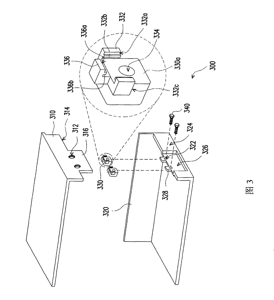
[0030] image 3 It is a schematic diagram of the electronic device according to the first embodiment of the present invention. Please refer to image 3 , the electronic device 300 of this embodiment includes a first casing 310 , a second casing 320 , a plurality of assembly parts 330 and a plurality of locking parts 340 . The first casing 310 has at least one first joint portion 312 ( image 3 Schematically shown as two), the second casing 320 has at least one second joint portion 322 ( image 3 are schematically shown as two), and each assembly part 330 has a plurality of assembly parts 332 and a locking part 334, wherein the assembly part 332 is used to combine with the second casing 320, so that the assembly part 330 is fixed on the first On the second casing 320 . The locking member 340 is used for passing through the first joint portion 312 and the second joint portion 322 which coincide with each other and locked into the locking portion 334 when the first casing 310...
no. 2 example
[0041] This embodiment is substantially the same as the first embodiment, and the same or similar element numbers represent the same or similar elements. Figure 5 is an exploded schematic view of the assembly of the second embodiment of the present invention, and Image 6 for Figure 5 Schematic diagram of the assembly. Please also refer to Figure 5 and Image 6 Unlike the first embodiment, the assembly 330' of this embodiment includes a body 330a and a copper pillar 330b, the assembly hole is formed on the copper pillar 330b and the copper pillar 330b is embedded in the body 330a to A locking portion 334' is formed. Specifically, the copper post 330b is heated first, and then the heated copper post 330b is inserted into the body 330a. Because the material of the main body 330a is plastic, the heated copper post 330b will melt the main body 330a slightly, and after the copper post 330b cools down, the copper post 330b is fixed in the main body 330a.
[0042] Figure 7...
no. 3 example
[0044] Figure 8 is a schematic diagram of the second casing of the electronic device according to the third embodiment of the present invention, and Figure 9 is a schematic diagram of the assembly of this embodiment. Please also refer to Figure 8 and Figure 9 , the second casing 320' has an inner surface 324' and at least one rib 329, and the rib 329 protrudes from the inner surface 324'. The assembly 330" has a bottom surface 338 in contact with the convex rib 329. In addition, the convex rib 329 further has a first positioning structure 329a, and the bottom surface 338 of the assembly 330" is provided with a second positioning structure 338a, and the first positioning structure 338a of this embodiment One positioning structure 329a is a groove, and the second positioning structure 338a is a protrusion, wherein when the assembly 330" is assembled on the second casing 320', the rib 329 supports the assembly 330", and the first positioning structure 329a and The combina...
PUM
 Abstract
Description
Claims
Application Information