
Improved ratchet ring spanner

A ring wrench and ratchet technology, applied to wrenches, manufacturing tools, wrenches, etc., can solve the problems of inconvenient use, affecting the strength of the handle 81, and the inability to increase the torque of the ratchet block 91, etc., to increase the number and area of ​​teeth, large torque, The effect of increasing the width

Inactive Publication Date: 2005-08-17
魏宏因
View PDF0 Cites 0 Cited by
  • Summary
  • Abstract
  • Description
  • Claims
  • Application Information

AI Technical Summary

Problems solved by technology

However, if the user is in a dark place, the user will not be able to see the marking arrow, and will not be able to determine the driving direction of the one-way ratchet mechanism 9, causing inconvenience in use.
[0004] Furthermore, the size of the ratchet block 91 of the above-mentioned ratchet mechanism 9 is limited by the width W' of the accommodating groove 83, and the size of the accommodating groove 83 is limited by the width of the handle 81 and cannot be increased arbitrarily, so that the ratchet The torsional force that the gear block 91 can bear cannot be improved
If the width of the accommodating groove 83 is increased rashly, the strength of the handle 81 will be affected

Method used


Image

  • Improved ratchet ring spanner
  • Improved ratchet ring spanner
  • Improved ratchet ring spanner

Examples


Embodiment Construction

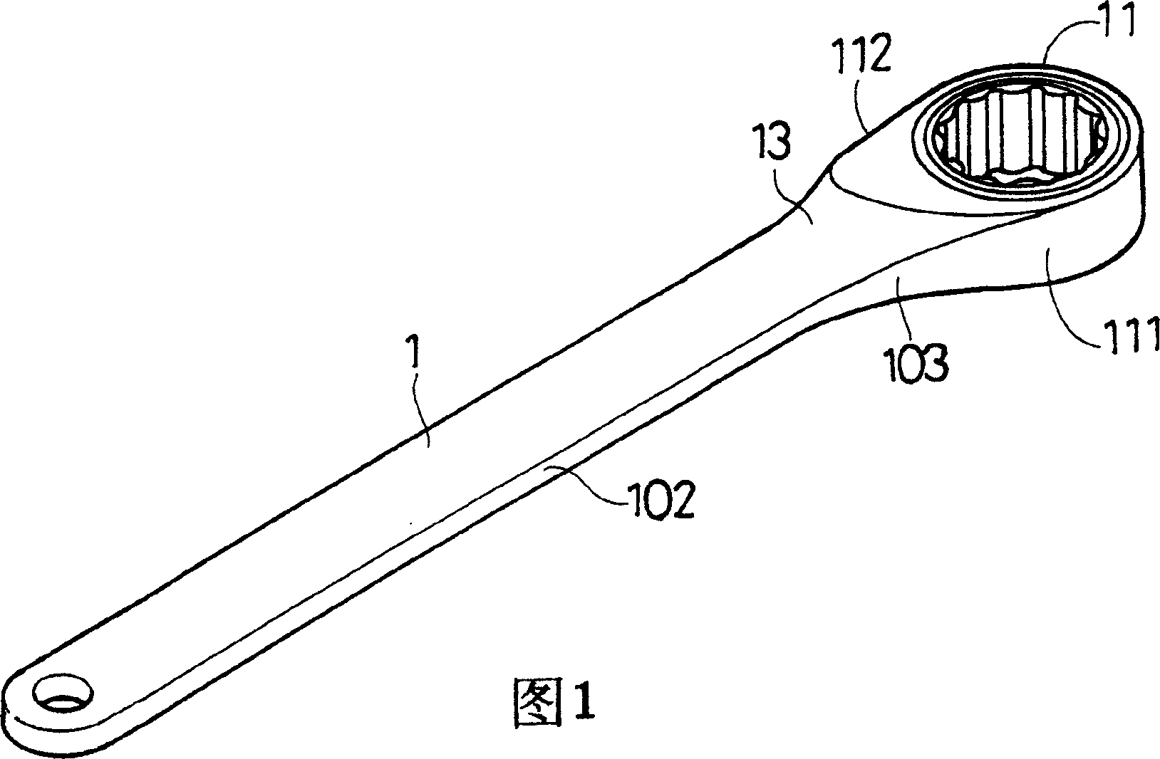
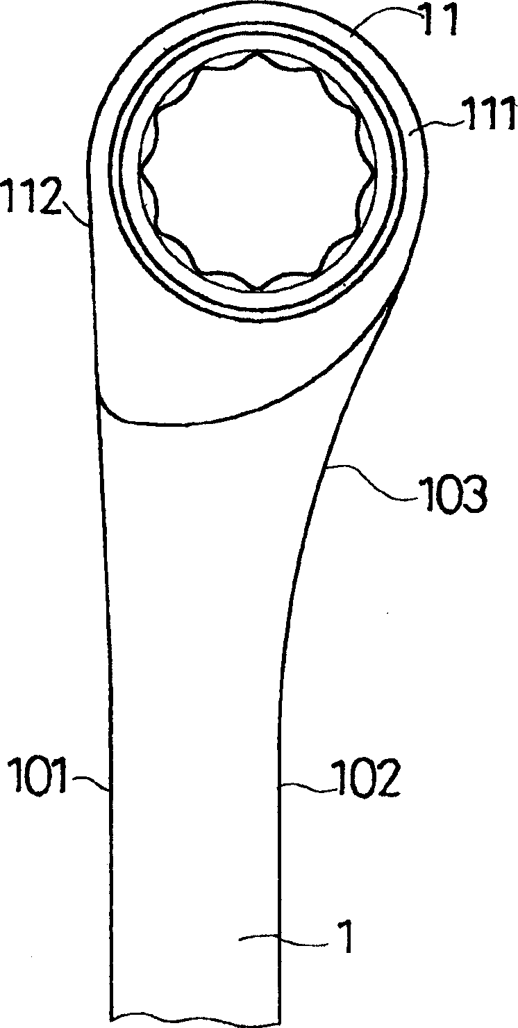
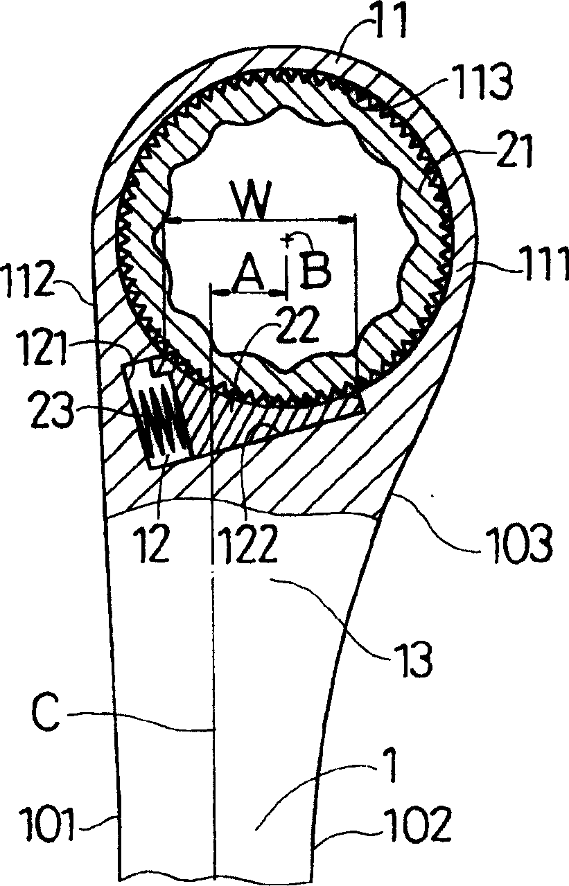
[0017] Please refer to Figure 1 to image 3 , the present invention has a handle 1, the handle 1 has a first side 101 and a second side 102, the handle 1 also has a head 11, the head 11 has a groove 113 for setting a ratchet 21. Between the handle 1 and the head 11 there is an accommodating groove 12 for setting a ratchet block 22. The accommodating groove 12 has a side surface 121 and a bottom surface 122 perpendicular to each other. The side surface 121 is located adjacent to the accommodating groove 12. One side of the first side 101 . The bottom surface 122 is for the ratchet block 22 to lean against and slide thereon, and a spring 23 is disposed between the side surface 121 and the ratchet block 22 to push the ratchet block 22 to engage with the ratchet wheel 21 under normal conditions. There is a distance A between the center point B of the head 11 and the centerline C of the handle 1, so that the head 11 protrudes laterally from the second side 102 of the handle 1 to f...


PUM


Abstract

An improved ratchet double offset ring wrench has a handle with a hand at its one end. THe head has a slot for setting a ratchet wheel, and there is one holding trough for arranging a ratchet block which is pushed elastically to mesh with the ratchet wheel normally. There is a spacing between the center of the head and the central line of the handle, and the head has a bulged part at one side of the central line. The present invention has easy-to-identify driving direction of the ratchet machanism, and the ratchet mechanism can bear relatively high twisting force.

Description

1. Technical field: [0001] The invention relates to a hand tool, in particular to an improved ratchet ring wrench. 2. Background technology: [0002] Such as Figure 5 As shown, it is a conventional one-way ratchet torx wrench. The handle 81 of the wrench 8 has a head 82 for a one-way ratchet mechanism 9. The center of the head 82 is located on the handle 81. On the centerline, the handle 81 has an accommodating groove 83 for setting a ratchet block 91 of the ratchet mechanism 9 therein. [0003] The conventional unidirectional ratchet torx wrench can only drive the ratchet in one direction, so an arrow is usually engraved on the handle 81 or the head 82 to indicate the driving direction. However, if the light is relatively dark, the user cannot see the marking arrow clearly, and has no way of distinguishing the driving direction of the one-way ratchet mechanism 9, which causes inconvenience in use. [0004] Furthermore, the size of the ratchet block 91 of the above-mentio...

Claims


Application Information

Patent Timeline
Patent Type & Authority Patents(China)
IPC IPC(8): B25B13/04B25B13/46
Inventor 魏宏因
Owner 魏宏因
Learn More